Nissan Murano: System Description / System. Can Communication System
SYSTEM DIAGRAM
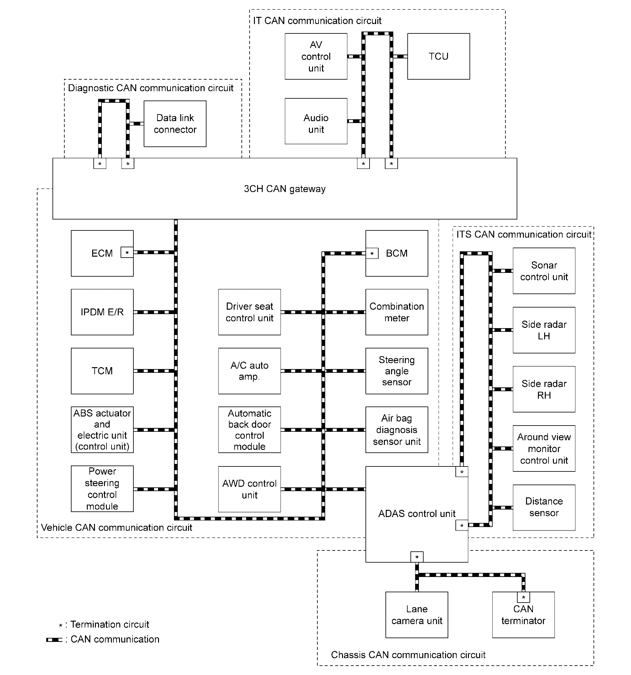
DESCRIPTION
-
CAN (Controller Area Network) is a serial communication line for real time application. It is an on-Nissan Murano vehicle multiplex communication line with high data communication speed and excellent error detection ability. Many electronic control units are equipped onto a Nissan Murano vehicle, and each control unit shares information and links with other control units during operation (not independent). In CAN communication, control units are connected with 2 communication lines (CAN-H line, CAN-L line) allowing a high rate of information transmission with less wiring. Each control unit transmits/receives data but selectively reads required data only.
-
The following control units include a gateway function and communicate signals between the different CAN communication circuits.
| CAN communication circuit | Gateway control unit | Reference |
|---|---|---|
|
Between the following circuit
|
3CH CAN gateway | System Description |
|
Between the following circuit
|
ADAS control unit | System Description |
CAN Communication Signal Generation
-
Termination circuits (resistors) are connected across the CAN communication system. When transmitting a CAN communication signal, each control unit passes a current to the CAN-H line and the current returns to the CAN-L line.

-
The current flows separately into the termination circuits connected across the CAN communication system and the termination circuits drop voltage to generate a potential difference between the CAN-H line and the CAN-L line.

 NOTE:
NOTE:
A signal with no current passage is called “Recessive” and one with current passage is called “Dominant”.
-
The system produces digital signals for signal communications, by using the potential difference.

The Construction of CAN Communication Signal (Message)

| No. | Message name | Description |
|---|---|---|
| 1 | Start of frame (1 bit) | Start of message. |
| 2 | Arbitration of field (11 bit) | Priorities of message-sending are shown when there is a possibility that multiple messages are sent at the same time. |
| 3 | Control field (6 bit) | Signal quantity in data field is shown. |
| 4 | Data field (0-64 bit) | Actual signal is shown. |
| 5 | CRC field (16 bit) |
|
| 6 | ACK field (2 bit) | The completion of normal reception is sent to the transmitting control unit. |
| 7 | End of frame (7 bit) | End of message. |
CAN COMMUNICATION LINE
The CAN communication line is a twisted pair wire consisting of strands of CAN-H  and CAN-L
  and has noise immunity.

NOTE:
The CAN communication system has the characteristics of noise-resistant because this system produces digital signals by using the potential difference between the CAN-H line and the CAN-L line and has the twisted pair wire structure.
Since the CAN-H line and the CAN-L line are always adjacent to each other, the same degree of noise occurs, respectively, when a noise occurs. Although the noise changes the voltage, the potential difference between the CAN-H line and the CAN-L line is insensitive to noise. Therefore, noise-resistant signals can be obtained.

CAN SIGNAL COMMUNICATIONS
Each control unit of the CAN communication system transmits signals through the CAN communication control circuit included in the control unit and receives only necessary signals from each control unit to perform various kinds of control.
-
Example: Transmitted signals

-
Example: Received signals

NOTE:
The above signal names and signal communications are provided for reference purposes. For CAN communications signals of this Nissan Murano vehicle, refer to CAN Communication Signal Chart.
CAN communication control circuit is incorporated into the control unit and transmits/receives CAN communication signals.

| Component | System description |
|---|---|
| CAN controller | It controls CAN communication signal transmission and reception, error detection, etc. |
| Transceiver IC | It converts digital signal into CAN communication signal, and CAN communication signal into digital signal. |
| Noise filter | It eliminates noise of CAN communication signal. |
|
Termination circuit* (Resistance of approx. 120 Ω) |
Generates a potential difference between CAN-H and CAN-L. |
*: These are the only control units wired with both ends of CAN communication system.
Determine CAN system type from the following specification chart.
NOTE:
Refer to Trouble Diagnosis Flow Chart for how to use CAN system specification chart.
| Body type | Wagon | ||||||||
|---|---|---|---|---|---|---|---|---|---|
| Axle | FWD | AWD | |||||||
| Engine | VQ35DE | ||||||||
| Transmission | CVT | ||||||||
| Brake control | VDC | ||||||||
| Around view monitor system | X | X | X | X | X | X | X | ||
| Automatic back door system | X | X | X | X | X | ||||
| Automatic drive positioner | X | X | X | X | |||||
| Telematics system | X | X | |||||||
| CAN system type | 1 | 2 | 3 | 4 | 5 | 6 | 7 | 8 | 9 |
| Nissan Murano Vehicle CAN communication unit | |||||||||
| ECM | X | X | X | X | X | X | X | X | X |
| IPDM E/R | X | X | X | X | X | X | X | X | X |
| TCM | X | X | X | X | X | X | X | X | X |
| ABS actuator and electric unit (control unit) | X | X | X | X | X | X | X | X | X |
| Power steering control module | X | X | X | X | X | X | X | X | X |
| 3CH CAN gateway | X | X | X | X | X | X | X | X | X |
| Driver seat control unit | X | X | X | X | |||||
| A/C auto amp. | X | X | X | X | X | X | X | X | X |
| ADAS control unit | X | X | X | X | X | X | X | X | X |
| Automatic back door control module | X | X | X | X | X | ||||
| AWD control unit | X | X | X | X | X | ||||
| Air bag diagnosis sensor unit | X | X | X | X | X | X | X | X | X |
| Combination meter | X | X | X | X | X | X | X | X | X |
| Steering angle sensor | X | X | X | X | X | X | X | X | X |
| BCM | X | X | X | X | X | X | X | X | X |
| ITS CAN communication unit | |||||||||
| ADAS control unit | X | X | X | X | X | X | X | X | X |
| Around view monitor control unit | X | X | X | X | X | X | X | ||
| Sonar control unit | X | X | X | X | X | X | X | X | X |
| Side radar RH | X | X | X | X | X | X | X | X | X |
| Side radar LH | X | X | X | X | X | X | X | X | X |
| Distance sensor | X | X | X | X | X | X | X | X | X |
| Chassis CAN communication unit | |||||||||
| ADAS control unit | X | X | X | X | X | X | X | X | X |
| Lane camera unit | X | X | X | X | X | X | X | X | X |
| IT CAN communication unit | |||||||||
| 3CH CAN gateway | X | X | X | X | X | X | X | X | X |
| AV control unit or Audio unit | X | X | X | X | X | X | X | X | X |
| TCU | X | X | |||||||
| Diagnostic CAN communication unit | |||||||||
| 3CH CAN gateway | X | X | X | X | X | X | X | X | X |
| Data link connector | X | X | X | X | X | X | X | X | X |
×: Applicable
VEHICLE EQUIPMENT IDENTIFICATION INFORMATION
NOTE:
Check CAN system type from the vehicle shape and equipment.

|
Side camera LH | |
Automatic back door switch |  |
Seat memory switches |
 |
Telematics switch | ||||
 |
With around view monitor system |  |
With automatic back door |  |
With automatic drive positioner |
 |
With telematics system |
Refer to How to Use CAN Communication Signal Chart for how to use CAN communication signal chart.
NOTE:
Refer to Abbreviation List for the abbreviations of the connecting units.
T: Transmit R: Receive
| Signal name | ECM | IPDM-E | TCM | ABS | EPS/DAST3 | AV | 3ch CGW | HVAC | PWBD | TCU | 4WD | A-BAG | M&A | STRG | BCM | ICC | ADP | AVM | LASER | RDR-L | RDR-R | SONAR | LANE |
|---|---|---|---|---|---|---|---|---|---|---|---|---|---|---|---|---|---|---|---|---|---|---|---|
| A/C compressor request signal | T | R | |||||||||||||||||||||
| Accelerator pedal position signal | T | R | R | R | R | ||||||||||||||||||
| ASCD operation signal | T | R | |||||||||||||||||||||
| ASCD status signal | T | R | |||||||||||||||||||||
| Closed throttle position signal | T | R | R | ||||||||||||||||||||
| Cooling fan speed request signal | T | R | |||||||||||||||||||||
| Engine and CVT integrated control signal | T | R | |||||||||||||||||||||
| R | T | ||||||||||||||||||||||
| Engine coolant temperature signal | T | R | R | R | |||||||||||||||||||
| Engine speed signal | T | R | R | R | R | R | |||||||||||||||||
| Engine status signal | T | R | R | R | R | R | |||||||||||||||||
| Fuel consumption monitor signal | T | R | R | ||||||||||||||||||||
| Fuel filler cap warning display signal | T | R | |||||||||||||||||||||
| ICC brake switch signal | T | R | |||||||||||||||||||||
| ICC operation signal | R | R | T | R | |||||||||||||||||||
| ICC prohibition signal | T | R | |||||||||||||||||||||
| ICC steering switch signal | T | R | |||||||||||||||||||||
| Malfunction indicator lamp signal | T | R | R | ||||||||||||||||||||
| R | T | ||||||||||||||||||||||
| Oil pressure warning lamp signal | T | R | R | ||||||||||||||||||||
| Power generation command value signal | T | R | |||||||||||||||||||||
| Stop lamp switch signal | T | R | |||||||||||||||||||||
| R | T | ||||||||||||||||||||||
| T | R | R | R | ||||||||||||||||||||
| A/C compressor feedback signal | R | T | R | R | |||||||||||||||||||
| Front wiper position signal | T | R | |||||||||||||||||||||
| High beam status signal | R | T | R | ||||||||||||||||||||
| Hood switch signal | T | R | |||||||||||||||||||||
| Low beam status signal | R | T | R | ||||||||||||||||||||
| Push-button ignition switch status signal | T | R | |||||||||||||||||||||
| CVT fluid temperature | R | T | |||||||||||||||||||||
| CVT ratio signal | T | R | |||||||||||||||||||||
| CVT position indicator signal | T | R | R | R | R | R | R | R | |||||||||||||||
| CVT self-diagnosis signal | R | T | |||||||||||||||||||||
| Current gear position signal | R | T | R | ||||||||||||||||||||
| Input speed signal | R | T | R | R | R | ||||||||||||||||||
| Manual mode shift refusal signal | T | R | |||||||||||||||||||||
| N range signal | T | R | R | ||||||||||||||||||||
| Next gear position signal | R | T | |||||||||||||||||||||
| Output shaft revolution signal | R | T | R | ||||||||||||||||||||
| P range signal | T | R | |||||||||||||||||||||
| R range signal | T | R | |||||||||||||||||||||
| Shift position signal | R | T | R | R | R | R | R | ||||||||||||||||
| Shift schedule signal | R | T | |||||||||||||||||||||
| ABS malfunction signal | R | T | R | ||||||||||||||||||||
| ABS operation signal | R | T | R | R | |||||||||||||||||||
| ABS warning lamp signal | T | R | R | R | |||||||||||||||||||
| Brake warning lamp signal | T | R | |||||||||||||||||||||
| R | T | ||||||||||||||||||||||
| Decel G sensor signal | T | R | |||||||||||||||||||||
| I-LI buzzer request signal | T | R | |||||||||||||||||||||
| I-LI condition signal | T | R | |||||||||||||||||||||
| I-LI malfunction signal | T | R | |||||||||||||||||||||
| I-LI meter indication request signal | T | R | |||||||||||||||||||||
| I-LI operation signal | T | R | |||||||||||||||||||||
| Warning system switch signal | T | R | |||||||||||||||||||||
| T | R | ||||||||||||||||||||||
| R | T | ||||||||||||||||||||||
| Rear LH wheel speed signal | T | R | |||||||||||||||||||||
| Rear RH wheel speed signal | T | R | |||||||||||||||||||||
| Side G sensor signal | T | R | R | ||||||||||||||||||||
| TCS malfunction signal | T | R | |||||||||||||||||||||
| TCS operation signal | R | R | T | R | |||||||||||||||||||
| VDC malfunction signal | T | R | R | ||||||||||||||||||||
| VDC OFF indicator lamp signal | T | R | R | ||||||||||||||||||||
| VDC OFF switch signal | T | R | |||||||||||||||||||||
| VDC operation signal | R | R | T | R | |||||||||||||||||||
| VDC warning lamp signal | T | R | |||||||||||||||||||||
| Yaw rate signal | T | R | R | ||||||||||||||||||||
| Nissan Murano Vehicle speed signal | R | T | R | R | R | R | R | R | R | R | |||||||||||||
| R | R | R | R | R | R | R | T | R | R | R | |||||||||||||
| EPS operation signal | R | T | |||||||||||||||||||||
| Hydraulic pump electric power steering warning lamp signal | T | R | |||||||||||||||||||||
| A/C switch operation signal | T | R | |||||||||||||||||||||
| Camera switch signal | T | R | |||||||||||||||||||||
| Rear window defogger switch signal | T | R | |||||||||||||||||||||
| System setting signal | T | R | |||||||||||||||||||||
| R | T | ||||||||||||||||||||||
| Voice recognition signal | T | R | |||||||||||||||||||||
| A/C display signal | R | T | |||||||||||||||||||||
| A/C evaporator temperature signal | R | T | |||||||||||||||||||||
| A/C ON signal | R | T | |||||||||||||||||||||
| Ambient sensor signal | T | R | |||||||||||||||||||||
| Blower fan ON signal | R | T | |||||||||||||||||||||
| Target A/C evaporator temperature signal | R | T | |||||||||||||||||||||
| Hazard request signal | T | R | |||||||||||||||||||||
| AWD signal | R | T | |||||||||||||||||||||
| AWD warning icon/display signal | T | R | |||||||||||||||||||||
| Crash information signal | R | T | |||||||||||||||||||||
| Brake fluid level switch signal | R | T | |||||||||||||||||||||
| Distance to empty signal | R | T | |||||||||||||||||||||
| Fuel filler cap warning reset signal | R | T | |||||||||||||||||||||
| Fuel level low warning signal | R | T | |||||||||||||||||||||
| Fuel level sensor signal | R | T | |||||||||||||||||||||
| Manual mode shift down signal | R | T | |||||||||||||||||||||
| Manual mode shift up signal | R | T | |||||||||||||||||||||
| Manual mode signal | R | T | |||||||||||||||||||||
| Non-manual mode signal | R | T | |||||||||||||||||||||
| Odometer signal | T | R | |||||||||||||||||||||
| Parking brake switch signal | R | R | R | T | R | R | |||||||||||||||||
| Seat belt buckle switch signal (driver side) | T | R | |||||||||||||||||||||
| Sleep-ready signal | T | R | |||||||||||||||||||||
| T | R | ||||||||||||||||||||||
| T | R | ||||||||||||||||||||||
| System selection signal | T | R | |||||||||||||||||||||
| Wake up signal | T | R | |||||||||||||||||||||
| T | R | ||||||||||||||||||||||
| Steering angle sensor malfunction signal | R | R | T | R | R | ||||||||||||||||||
| Steering angle sensor signal | R | R | R | R | T | R | R | ||||||||||||||||
| Steering angle speed signal | R | T | R | ||||||||||||||||||||
| Steering calibration signal | R | T | R | ||||||||||||||||||||
| Automatic back door request signal | R | T | |||||||||||||||||||||
| Back door lock status signal | R | T | |||||||||||||||||||||
| Buzzer request signal | R | T | |||||||||||||||||||||
| T | R | ||||||||||||||||||||||
| Buzzer output signal | R | T | |||||||||||||||||||||
| R | T | ||||||||||||||||||||||
| Day time running light request signal | R | R | T | R | |||||||||||||||||||
| Dimmer signal | R | T | R | ||||||||||||||||||||
| Door switch signal | R | R | R | R | T | R | R | ||||||||||||||||
| Door unlock signal | T | R | |||||||||||||||||||||
| Front fog light request signal | R | R | T | R | |||||||||||||||||||
| Front wiper request signal | R | R | R | T | R | ||||||||||||||||||
| Handle position signal | T | R | |||||||||||||||||||||
| High beam request signal | R | R | R | T | R | ||||||||||||||||||
| Horn reminder signal | R | T | |||||||||||||||||||||
| Ignition switch ON signal | R | T | |||||||||||||||||||||
| T | R | ||||||||||||||||||||||
| Ignition switch signal | R | R | T | R | |||||||||||||||||||
| Intelligent Key system warning display signal | R | T | |||||||||||||||||||||
| Interlock/PNP switch signal | R | T | |||||||||||||||||||||
| T | R | ||||||||||||||||||||||
| Key ID signal | R | T | R | ||||||||||||||||||||
| Low beam request signal | R | R | T | R | |||||||||||||||||||
| Low tire pressure warning lamp signal | R | T | |||||||||||||||||||||
| Meter TPMS display signal | R | T | |||||||||||||||||||||
| R | T | ||||||||||||||||||||||
| Meter ring illumination request signal | R | T | |||||||||||||||||||||
| Oil pressure switch signal | R | T | |||||||||||||||||||||
| T | R | R | |||||||||||||||||||||
| Position light request signal | R | R | R | T | R | ||||||||||||||||||
| Rear window defogger control signal | R | R | T | ||||||||||||||||||||
| R | T | R | |||||||||||||||||||||
| Sleep wake up signal | R | R | R | R | R | T | R | ||||||||||||||||
| Starter control relay signal | R | T | |||||||||||||||||||||
| Starter relay status signal | R | R | T | ||||||||||||||||||||
| T | R | ||||||||||||||||||||||
| Starting mode signal | R | T | R | ||||||||||||||||||||
| Theft warning horn request signal | R | T | |||||||||||||||||||||
| Back door switch signal | R | T | R | ||||||||||||||||||||
| Turn indicator signal | R | R | R | T | R | R | R | ||||||||||||||||
| Brake fluid pressure control signal | R | T | |||||||||||||||||||||
| BSW indicator signal | R | T | |||||||||||||||||||||
| FEB warning lamp signal | R | T | |||||||||||||||||||||
| I-LI ON indicator lamp signal | R | T | |||||||||||||||||||||
| R | R | T | |||||||||||||||||||||
| Lane departure warning lamp signal | R | T | |||||||||||||||||||||
| R | R | T | |||||||||||||||||||||
| Warning system ON indicator signal | T | R | |||||||||||||||||||||
| Sonar setting change signal | T | R | |||||||||||||||||||||
| View change signal | R | T | |||||||||||||||||||||
| Nissan Murano Vehicle detection signal | R | T | |||||||||||||||||||||
| R | T | ||||||||||||||||||||||
| Detected lane condition signal | R | T | |||||||||||||||||||||
| Lane camera status signal | R | T | |||||||||||||||||||||
| Lane departure buzzer operation signal | R | T | |||||||||||||||||||||
| LDW operation signal | R | T | |||||||||||||||||||||
| Sonar status signal | R | T |
 Component Parts. Can Terminator
Component Parts Location
Side radar RH
AWD control unit
AV control unit (With navigation system)
Audio unit (Without navigation system)
A/C auto amp...

Other information:
Nissan Murano (Z52) 2015-2024 Service Manual: Left Knee Air Bag Module
Exploded View 1. Left knee air bag module A. Refer to Removal and Installation. Front Removal and Installation WARNING: Before servicing the SRS, place the ignition switch in the OFF position, disconnect both battery terminals then wait at least three minutes...
Nissan Murano (Z52) 2015-2024 Service Manual: Front Fog Lamp
Exploded View 1. Front fog lamp 2. Front bumper fascia A. Front fog lamp harness connector Removal and Installation REMOVALPartially remove front fender protector. Refer to Exploded View. Disconnect harness connector from front fog lamp...
Categories
- Manuals Home
- Nissan Murano Owners Manual
- Nissan Murano Service Manual
- GAS STATION INFORMATION
- Tire rotation
- Shift lock release
- New on site
- Most important about car
Luggage hooks

When securing items using luggage hooks located on the back of the seat or side finisher do not apply a load over more than 6.5 lbs. (29 N) to a single hook.
The luggage hooks that are located on the floor should have loads less than 110 lbs. (490 N) to a single hook.