Nissan Murano: Automatic Drive Positioner :: Ecu Diagnosis Information / Driver Seat Control Unit
 NOTE:
NOTE:
The following table includes information (items) inapplicable to this Nissan Murano vehicle. For information (items) applicable to this vehicle, refer to CONSULT display items.
| Monitor Item | Condition | Value/Status | |
|---|---|---|---|
| STARTER SW | Ignition position | Cranking | ON |
| Other than above | OFF | ||
| SET SW | Set switch | Push | ON |
| Release | OFF | ||
| MEMORY SW 1 | Memory switch 1 | Push | ON |
| Release | OFF | ||
| MEMORY SW 2 | Memory switch 2 | Push | ON |
| Release | OFF | ||
| DETENT SW | CVT selector lever | P position | OFF |
| Other than above | ON | ||
| STEERING STATUS | Power supply position of BCM | LOCK | LOCK |
| Other than the above | UNLOCK | ||
| SLIDE SW–FR | Sliding switch (forward) | Operate | ON |
| Release | OFF | ||
| SLIDE SW–RR | Sliding switch (backward) | Operate | ON |
| Release | OFF | ||
| RECLN SW–FR | Reclining switch (forward) | Operate | ON |
| Release | OFF | ||
| RECLN SW–RR | Reclining switch (backward) | Operate | ON |
| Release | OFF | ||
| LIFT FR SW–UP | Lifting switch front (upward) | Operate | ON |
| Release | OFF | ||
| LIFT FR SW–DN | Lifting switch front (downward) | Operate | ON |
| Release | OFF | ||
| LIFT RR SW–UP | Lifting switch rear (upward) | Operate | ON |
| Release | OFF | ||
| LIFT RR SW–DN | Lifting switch rear (downward) | Operate | ON |
| Release | OFF | ||
| TILT SW-UP | Tilt switch | Upward | ON |
| Other than above | OFF | ||
| TILT SW-DOWN | Tilt switch | Downward | ON |
| Other than above | OFF | ||
| TELESCO SW-FR | Telescopic switch | Forward | ON |
| Other than above | OFF | ||
| TELESCO SW-RR | Telescopic switch | Backward | ON |
| Other than above | OFF | ||
| MIR CON SW–UP | Mirror switch | Up | ON |
| Other than above | OFF | ||
| MIR CON SW–DN | Mirror switch | Down | ON |
| Other than above | OFF | ||
| MIR CON SW–RH | Mirror switch | Right | ON |
| Other than above | OFF | ||
| MIR CON SW–LH | Mirror switch | Left | ON |
| Other than above | OFF | ||
| MIR CHNG SW–R | Select switch | Right | ON |
| Other than above | OFF | ||
| MIR CHNG SW–L | Select switch | Left | ON |
| Other than above | OFF | ||
| TILT PULSE | Tilt position | Upward | The numeral value decreases * |
| Downward | The numeral value increases * | ||
| Other than above | No change to numeral value* | ||
| TELESCO PULSE | Telescopic position | Forward | The numeral value decreases * |
| Backward | The numeral value increases * | ||
| Other than above | No change to numeral value* | ||
| MIR/SEN RH U–D | Door mirror RH |
Change between 3.4 (close to peak) 0.6 (close to valley) |
|
| MIR/SEN RH R–L | Door mirror RH |
Change between 3.4 (close to left edge) 0.6 (close to right edge) |
|
| MIR/SEN LH U–D | Door mirror LH |
Change between 3.4 (close to peak) 0.6 (close to valley) |
|
| MIR/SEN LH R–L | Door mirror LH |
Change between 0.6 (close to left edge) 3.4 (close to right edge) |
|
| SLIDE PULSE | Seat sliding | Forward | The numeral value decreases * |
| Backward | The numeral value increases* | ||
| Other than above | No change to numeral value* | ||
| RECLN PULSE | Seat reclining | Forward | The numeral value decreases* |
| Backward | The numeral value increases * | ||
| Other than above | No change to numeral value* | ||
| LIFT FR PULSE | Seat lifter (front) | Upward | The numeral value decreases * |
| Downward | The numeral value increases * | ||
| Other than above | No change to numeral value* | ||
| LIFT RR PULSE | Seat lifter (rear) | Upward | The numeral value decreases * |
| Downward | The numeral value increases * | ||
| Other than above | No change to numeral value* | ||
| Nissan Murano Vehicle SPEED | The condition of vehicle speed is displayed | km/h | |
| P RANG SW CAN | CVT selector lever | P position | ON |
| Other than above | OFF | ||
| R RANGE (CAN) | CVT selector lever | R position | ON |
| Other than above | OFF | ||
| DOOR SW-FL | Driver door | Open | OPEN |
| Close | CLOSED | ||
| DOOR SW-FR | Passenger door | Open | OPEN |
| Close | CLOSED | ||
| IGN ON SW | Ignition switch | ON position | ON |
| Other than above | OFF | ||
| ACC ON SW | Ignition switch | ACC or ON position | ON |
| Other than above | OFF | ||
| KYLS DR UNLK | Intelligent Key or driver side door request switch | ON | ON |
| OFF | OFF | ||
| KEYLESS ID | UNLOCK button of Intelligent Key is pressed | 1, 2, 3, 4 or 5 | |
| VHCL SPEED (ABS) | CAN signal from ABS | Received | ON |
| Not received | OFF | ||
| HANDLE | Driving position | LHD | |
| RHD | |||
| TRANSMISSION | Transmission type | CVT | |
| KEY NUMBER |
This item is displayed, but cannot be monitored |
KEY 1 | |
| KEY 1 |
This item is displayed, but cannot be monitored |
NO REG | |
| KEY 2 |
This item is displayed, but cannot be monitored |
NO REG | |
| KEY 3 |
This item is displayed, but cannot be monitored |
NO REG | |
| KEY 4 |
This item is displayed, but cannot be monitored |
NO REG | |
*: The value at the position attained when the battery is connected is regarded as 32768.
TERMINAL LAYOUT
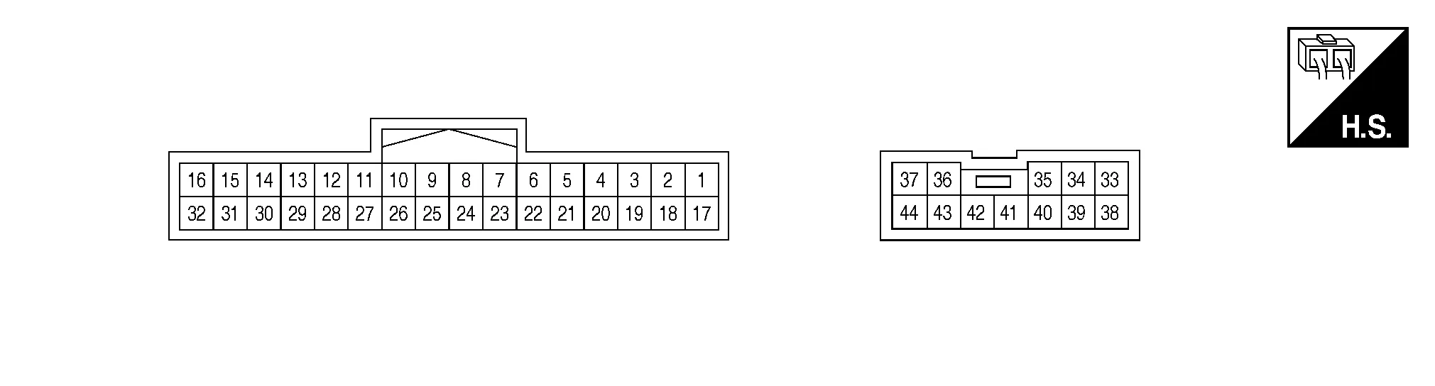
PHYSICAL VALUES
|
Terminal No. (wire color) | Description | Condition |
Voltage (Approx.) | |||
|---|---|---|---|---|---|---|
| + | - | Signal name | Input/Output | |||
|
5 (W) |
Ground | Sensor power supply | Output | — | Battery voltage | |
|
6 (R) |
Ground | Lifting switch (rear) down signal | Input |
Seat lifting switch (rear) |
Operate (down) |
0V |
| Release | Battery voltage | |||||
|
7 (Y) |
Ground | Lifting switch (front) down signal | Input | Seat lifting switch (front) |
Operate (down) |
0V |
| Release | Battery voltage | |||||
|
8 (BR) |
Ground | Reclining switch backward signal | Input | Reclining switch |
Operate (backward) |
0V |
| Release | Battery voltage | |||||
|
9 (SB) |
Ground | Sliding switch backward signal | Input | Sliding switch |
Operate (backward) |
0V |
| Release | Battery voltage | |||||
|
10 (G) |
Ground | Memory indicator 2 signal | Output | Memory indicator 2 | Illuminate | 1V |
| Other than above | Battery voltage | |||||
|
11 (GR) |
Ground | Memory switch 2 signal | Input | Memory switch 2 | Press | 0V |
| Other than above | 5V | |||||
|
12 (W) |
Ground | Telescopic sensor signal | Input | Telescopic | Operate |
|
| Other than above | 0V or 5V | |||||
|
13 (G) |
Ground | Reclining sensor signal | Input | Seat reclining | Operate |
|
| Stop | 0V or 5V | |||||
|
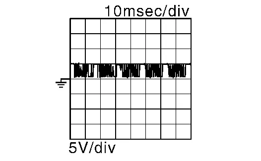
15 (SB) |
Ground | UART communication (TX/RX) | Input | Ignition switch ON |
|
|
|
16 (P) |
— | CAN-High | — | — | — | |
|
21 (L) |
Ground | Set switch signal | Input | Set switch | Press | 0V |
| Other than above | 5V | |||||
|
22 (V) |
Ground | Lifting switch (rear) up signal | Input | Lifting switch (rear) |
Operate (up) |
0V |
| Release | Battery voltage | |||||
|
23 (G) |
Ground | Lifting switch (front) up signal | Input | Lifting switch (front) |
Operate (up) |
0V |
| Release | Battery voltage | |||||
|
24 (P) |
Ground | Reclining switch forward signal | Input | Reclining switch |
Operate (forward) |
0V |
| Release | Battery voltage | |||||
|
25 (L) |
Ground | Sliding switch forward signal | Input | Sliding switch |
Operate (forward) |
0V |
| Release | Battery voltage | |||||
|
26 (Y) |
Ground | Memory indicator 1 signal | Output | Memory indicator 1 | Illuminate | 1V |
| Other than above | Battery voltage | |||||
|
27 (V) |
Ground | Memory switch 1 signal | Input | Memory switch 1 | Press | 0V |
| Other than above | 5V | |||||
|
28 (BR) |
Ground | Tilt sensor signal | Input | Tilt | Operate |
|
| Other than above | 0V or 5V | |||||
|
29 (R) |
Ground | Lifting sensor (rear) signal | Input | Seat lifting (rear) | Operate |
|
| Stop | 0V or 5V | |||||
|
30 (Y) |
Ground | Lifting sensor (front) signal | Input | Seat lifting (front) | Operate |
|
| Stop | 0V or 5V | |||||
|
31 (LG) |
Ground | Sliding sensor signal | Input | Seat sliding | Operate |
|
| Stop | 0V or 5V | |||||
|
32 (W) |
— | CAN-Low | — | — | — | |
|
34 (SB) |
Ground | Lifting motor LH (front) up signal | Output | Seat lifting (front) |
Operate (up) |
Battery voltage |
| Stop | 0V | |||||
|
35 (V) |
Ground | Reclining motor LH forward signal | Output | Seat reclining |
Operate (forward) |
Battery voltage |
| Release | 0V | |||||
|
36 (W) |
Ground | Sliding motor LH backward signal | Output | Seat sliding |
Operate (backward) |
Battery voltage |
| Stop | 0V | |||||
|
37 (R) |
Ground | Battery power supply | Input | — | Battery voltage | |
|
39 (B) |
Ground | Ground | — | — | 0V | |
|
40 (L) |
Ground | Lifting motor LH (rear) down signal | Output | Seat lifting (rear) |
Operate (down) |
Battery voltage |
| Stop | 0V | |||||
|
41 (Y) |
Ground | Lifting motor LH (rear) up signal | Output | Seat lifting (rear) |
Operate (up) |
Battery voltage |
| Stop | 0V | |||||
|
42 (GR) |
Ground | Lifting motor LH (front) down signal | Output | Seat lifting (front) |
Operate (down) |
Battery voltage |
| Stop | 0 V | |||||
|
43 (BR) |
Ground | Reclining motor LH backward signal | Output | Seat reclining |
Operate (backward) |
Battery voltage |
| Stop | 0V | |||||
|
44 (G) |
Ground | Sliding motor LH forward signal | Output | Seat sliding |
Operate (forward) |
Battery voltage |
| Release | 0V | |||||

The fail-safe mode may be activated if the following symptoms are observed.
|
Operating in fail-safe mode | Malfunction Item | Related DTC | Diagnosis |
|---|---|---|---|
| Only manual functions operate normally. | CAN communication | U1000 | DTC Description |
| CONTROL UNIT | U1010 | DTC Description | |
| EEPROM | B2130 | DTC Description | |
| Only manual functions, except door mirror, operate normally. | UART communication | B2128 | DTC Description |
| Only manual functions, except seat sliding, operate normally. | Seat sliding output | B2112 | DTC Description |
| Only manual functions, except seat reclining, operate normally. | Seat reclining output | B2113 | DTC Description |
| Only manual functions, except steering tilt, operate normally. | Steering column tilt output | B2116 | DTC Description |
|
CONSULT display | Timing*1 | Item | Reference page | |
|---|---|---|---|---|
| Current malfunction | Previous malfunction | |||
|
CAN COMM CIRCUIT [U1000] |
0 | 1-39 | CAN communication | DTC Description |
|
CONTROL UNIT(CAN) [U1010] |
0 | 1-39 | Control unit | DTC Description |
|
SEAT SLIDE [B2112] |
0 | 1-39 | Seat slide motor output | DTC Description |
|
SEAT RECLINING [B2113] |
0 | 1-39 | Seat reclining motor output | DTC Description |
|
STEERING TILT [B2116] |
0 | 1-39 | Tilt motor output | DTC Description |
|
UART COMM [B2128] |
0 | 1-39 | UART communication | DTC Description |
|
EEPROM [B2130] |
0 | 1-39 | EEPROM | DTC Description |
*1: About timing
-
0: Current malfunction is present.
-
1-39: Displayed if any previous malfunction is present when current condition is normal. The numeral value increases by one at each IGN ON to OFF cycle from 1 to 39. The counter remains at 39 even if the number of cycles exceeds it. However, the counter is reset to 1 if any malfunction is detected again, the normal operation is resumed and the ignition switch from OFF to ON.

 Automatic Drive Positioner Control Unit
Reference Value
TERMINAL LAYOUTPHYSICAL VALUES
Terminal No.
(wire color) Description Condition
Voltage
(Approx.)
+ - Signal name Input/Output
1
(LG)
Ground
Tilt switch up signal
Input
Tilt switch
Operate
(up)
0V
Other than above
5V
2
(GR)
Ground
Select switch RH signal
Input
Select switch position
RH
0V
Neutral or LH
5V
3
(G)
Ground
Mirror switch up signal
Input
Mirror switch
Operated
(up)
0V
Other than above
5V
4
(P)
Ground
Mirror switch left signal
Input
Mirror switch
Operated
(left)
0V
Other than above
5V
5
(W)
Ground
Door mirror sensor RH up/down signal
Input
Door mirror RH position
Change between 3...
Other information:
Nissan Murano (Z52) 2015-2024 Service Manual: How to Set Srt Code
Description OUTLINEIn order to set all SRTs, the self-diagnoses as in the “SRT ITEM” table must have been performed at least once. Each diagnosis may require actual driving for a long period of time under various conditions.SRT ITEMThe table below shows required self-diagnostic items to set the SRT to “CMPLT”...
Nissan Murano (Z52) 2015-2024 Service Manual: Combination Switch Reading System
System Description SYSTEM DIAGRAMOUTLINE BCM reads the status of the combination switch (light, turn signal, wiper and washer) and recognizes the status of each switch. BCM has a combination of 5 output terminals (OUTPUT 1 - 5) and 5 input terminals (INPUT 1 - 5) and reads a maximum of 19 switch states...
Categories
- Manuals Home
- Nissan Murano Owners Manual
- Nissan Murano Service Manual
- GAS STATION INFORMATION
- System malfunction
- Jacking up vehicle and removing the damaged tire
- New on site
- Most important about car
Fuel gauge

The gauge indicates the approximate fuel level in the tank.
The gauge may move slightly during braking, turning, acceleration, or going up or down hills.
The gauge needle returns to 0 (Empty) after the ignition switch is placed in the OFF position.