
Nissan Murano: Automatic Drive Positioner :: Dtc/circuit Diagnosis / Sliding Motor
ACTIVE TEST
 CONSULT
-
Select “SEAT SLIDE” in “Active Test” mode of “AUTO DRIVE POS.”.
-
Check that the function operates normally.
| Test Item | Description | ||
|---|---|---|---|
| SEAT SLIDE | Off | Seat sliding | Stop |
| FR | Forward | ||
| RR | Backward | ||
Is the operation of relevant parts normal?
YES>>Inspection End.
NO>>Perform diagnosis procedure. Refer to Diagnosis Procedure.
CHECK SLIDING MOTOR LH POWER SUPPLY
CONSULT
-
Ignition switch ACC.
-
Select “SEAT SLIDE” in “Active Test” mode of “AUTO DRIVE POS.”.
-
Check voltage between driver seat control unit harness connector and ground.
(+) (-) Condition Voltage
(Approx.)Driver seat control unit Connector Terminal B210 36 Ground SEAT SLIDE Off 0V FR (forward) 0V RR (backward) Battery voltage 44 Off 0V FR (forward) Battery voltage RR (backward) 0V
Is the inspection result normal?
YES>>Replace sliding motor LH. Refer to Removal and Installation.
NO>>GO TO 2.
CHECK SLIDING MOTOR LH CIRCUIT
-
Ignition switch OFF.
-
Disconnect driver seat control unit and sliding motor LH.
-
Check continuity between driver seat control unit harness connector and sliding motor LH harness connector.
Driver seat control unit Sliding motor LH Continuity Connector Terminal Connector Terminal B210 36 B211 1 Yes 44 5 -
Check continuity between driver seat control unit harness connector and ground.
Driver seat control unit connector Ground Continuity Connector Terminal B210 36 No 44
Is the inspection result normal?
YES>>GO TO 3.
NO>>Repair or replace harness.
CHECK INTERMITTENT INCIDENT
Refer to Intermittent Incident.
Is the inspection result normal?
YES>>Replace driver seat control unit. Refer to Removal and Installation.
NO>>Repair or replace the malfunctioning part.
 Mirror Sensor. Lh
Component Function Check
DATA MONITOR
CONSULT
Select “MIR/SEN LH U-D”, “MIR/SEN LH R-L” in “Data Monitor” mode of “AUTO DRIVE POS.”...
 Tilt Motor
Component Function Check
ACTIVE TEST
CONSULT
Select “TILT MOTOR” in “Active Test” mode of “AUTO DRIVE POS.”.
Check that the function operates normally...
Other information:
Nissan Murano (Z52) 2015-2024 Service Manual: U0428 Steering Angle Sensor
DTC Description DTC DETECTION LOGIC DTC No. CONSULT screen terms (Trouble diagnosis content) DTC detection condition U0428 ST ANGLE SENSOR CALIBRATION (Steering angle sensor calibration) Diagnosis condition When ignition switch is ON Signal (terminal) — Threshold — Diagnosis delay time — POSSIBLE CAUSE Neutral position adjustment of steering angle sensor is not complete Steering angle sensor FAIL-SAFE Predicted course line is not displayed MOD (Moving Object Detection) function is stopped DTC Confirmation Procedure CHECK DTC PRIORITY If DTC U0428 is displayed with DTC U1232, first perform the diagnosis for DTC U1232...
Nissan Murano (Z52) 2015-2024 Service Manual: B2724 Sonar Control Unit
DTC Description DTC DETECTION LOGIC DTC No. CONSULT screen terms (Trouble diagnosis content) DTC detection condition B2724–23 SONAR CONTROL UNIT (Sonar control unit) — Diagnosis condition When ignition switch is ON Signal (terminal) — Threshold Sonar ECU internal failure (under voltage) Diagnosis delay time — B2724–24 Diagnosis condition When ignition switch is ON Signal (terminal) — Threshold Sonar ECU internal failure (over voltage) Diagnosis delay time — B2724–44 Diagnosis condition When ignition switch is ON Signal (terminal) — Threshold Sonar ECU internal failure (RAM failure) Diagnosis delay time — B2724–45 Diagnosis condition When ignition switch is ON Signal (terminal) — Threshold Sonar ECU internal failure (ROM failure) Diagnosis delay time — B2724–46 Diagnosis condition When ignition switch is ON Signal (terminal) — Threshold Sonar ECU internal failure (EEPROM failure) Diagnosis delay time — B2724–48 Diagnosis condition When ignition switch is ON Signal (terminal) — Threshold Sonar ECU internal failure (internal software execution failure) Diagnosis delay time — B2724–49 Diagnosis condition When ignition switch is ON Signal (terminal) — Threshold Sonar ECU internal failure (basic chip set failure) Diagnosis delay time — B2724–55 Diagnosis condition When ignition switch is ON Signal (terminal) — Threshold Sonar ECU internal failure (not configured) Diagnosis delay time — B2724–86 Diagnosis condition When ignition switch is ON Signal (terminal) — Threshold Sonar ECU internal failure (SPI comm failure) Diagnosis delay time — B2724–87 Diagnosis condition When ignition switch is ON Signal (terminal) — Threshold Sonar ECU internal failure (high side switch failure) Diagnosis delay time — POSSIBLE CAUSE Charging system malfunction Sonar control unit power supply or ground circuit Sonar control unit configuration Sonar control unit FAIL-SAFE Off indicator blinks periodically (500ms ON, 500ms OFF)...
Categories
- Manuals Home
- Nissan Murano Owners Manual
- Nissan Murano Service Manual
- Jacking up vehicle and removing the damaged tire
- Turning the AEB system on/off
- High Beam Assist (if so equipped)
- New on site
- Most important about car
Autolight system
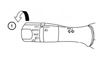
The autolight system allows the headlights to turn on and off automatically. The autolight system can:
Turn on the headlights, front parking, tail, license plate and instrument panel lights automatically when it is dark. Turn off all the lights (except daylight running lights) when it is light. Keep all the lights on for a period of time after you place the ignition switch in the OFF position and all doors are closed.