
Nissan Murano: Suspension / Rear Suspension :: Unit Removal and Installation. Rear Suspension Member
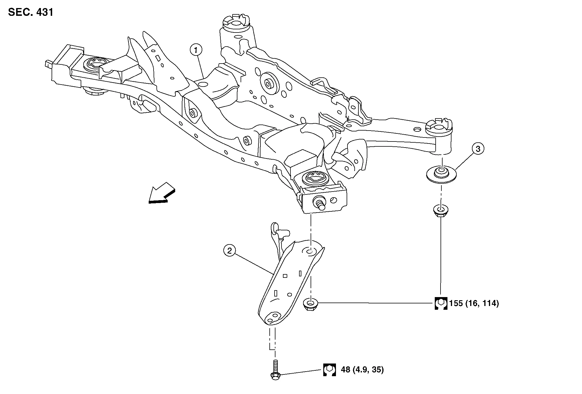
| 1. | Rear suspension member | 2. | Rear suspension member stay | 3. | Rear suspension member stopper |
 |
Front |
REMOVAL
Remove the front under cover. Refer to Removal and Installation.
Support the front of vehicle with a suitable jack.
WARNING:
Place a suitable jack under the center of the front suspension member.
CAUTION:
Do not damage the front suspension member with the suitable jack.
Remove the disc brake rotors (LH/RH). Refer to Removal and Installation.
Disconnect the harness connector from the rear wheel sensor harness.
Separate the harness from the rear suspension member.
Separate the harness from the rear suspension arms (LH/RH).
Remove the center exhaust tube. Refer to Exploded View.
For AWD Nissan Murano vehicles, remove the propeller shaft. Refer to Removal and Installation.
For AWD vehicles, remove the rear final drive. Refer to Removal and Installation.
Remove the stabilizer. Refer to Removal and Installation.
Separate the parking brake cables from the rear knuckles, from the Nissan Murano vehicle chassis, and from the rear suspension member. Refer to Exploded View.
Remove the rear lower links and the coil springs (LH/RH). Refer to Removal and Installation.
Remove the shock absorber lower bolts (LH/RH). Refer to Exploded View.
Set a suitable jack under the rear suspension member.
WARNING:
Place a suitable jack under the center of the rear suspension member.
CAUTION:
Do not damage the rear suspension member with the suitable jack.
Remove the rear suspension member stays from the Nissan Murano vehicle chassis (LH/RH).
Slowly lower the jack. Remove the rear suspension member, the rear suspension arms, the radius rods, the front lower links, and the rear knuckles from the Nissan Murano vehicle as a unit.
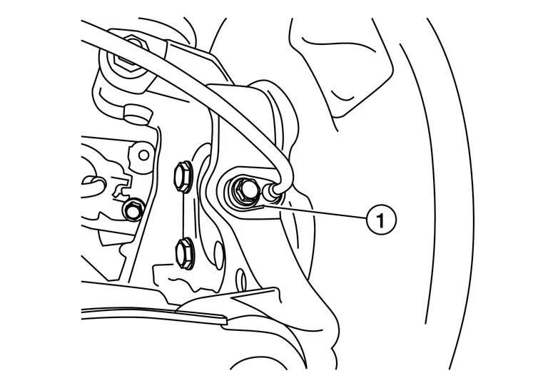
If necessary, remove bolt (1) and separate the rear wheel sensors from the rear knuckles (LH/RH). Refer to Removal and Installation.
CAUTION:
-
Pull out the rear wheel sensor being careful to turn it as little as possible. Do not pull on the wheel sensor harness.
-
Failure to remove the rear wheel sensor from the rear knuckle may result in damage to the rear wheel sensor.
If necessary, remove each rear knuckle with the parking brake components and the wheel hub and bearing as an assembly.
If necessary, remove the rear suspension arms (LH/RH). Refer to Exploded View.
If necessary remove the radius rods (LH/RH). Refer to Exploded View.
If necessary, remove the front lower links (LH/RH). Refer to Exploded View.
INSTALLATION
Installation is in the reverse order of the removal.
CAUTION:
-
Do not reuse the rear suspension arm nuts at the rear suspension member.
-
Do not reuse the rear lower link nuts.
-
Do not reuse the front lower link nuts.
-
Do not reuse exhaust gaskets.
-
Before installation, make sure there is no foreign material, such as iron fragments, adhered to the pick-up part of the rear wheel sensor.
-
When installing, make sure there is no foreign material, such as iron fragments, on and in the hole in the rear knuckle for the rear wheel sensor. Make sure no foreign material has been caught in the sensor rotor. Remove any foreign material and clean the mount.
-
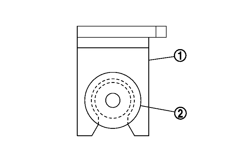
Do not twist the rear wheel sensor harness when installing the rear wheel sensor. Check that the grommet (2) is fully inserted into the bracket (1). Check that the rear wheel sensor harness is not twisted after installation.
-
Perform the final tightening of the parts under unladen conditions with the tires on level ground.
-
Check the rear wheel sensor harness for proper connection. Refer to Exploded View.
-
Adjust the parking brake operation (stroke). Refer to Inspection and Adjustment.
-
Check the wheel alignment. Refer to Inspection.
-
Adjust the neutral position of the steering angle sensor. Refer to Description.
-
For AWD Nissan Murano vehicles, check the rear differential gear oil level. Refer to Inspection.
 Rear Suspension Arm
Exploded View
1.
Rear suspension arm bushing
2.
Rear suspension member
3.
Rear knuckle
4.
Ball joint seat
5.
Cotter pin
6.
Stabilizer connecting rod
7...
 Rear Suspension :: Unit Disassembly and Assembly. Rear Shock Absorber
Exploded View
1.
Rear shock absorber
2.
Piston rod lock nut
3.
Shock absorber insulator
4.
Bound bumper
Front
Disassembly and Assembly
DISASSEMBLYCAUTION:
Do not damage the shock absorber piston rod when removing components from the shock absorber...
Other information:
Nissan Murano (Z52) 2015-2024 Owners Manual: Power Windows
WARNING Make sure that all passengers have their hands, etc., inside the vehicle while it is in motion and before closing the windows. Use the window lock switch to prevent unexpected use of the power windows. To help avoid risk of injury or death through unintended operation of the vehicle and/or its systems, including entrapment in windows or inadvertent door lock activation, do not leave children, people who require the assistance of others or pets unattended in your vehicle...
Nissan Murano (Z52) 2015-2024 Service Manual: Seat Belt :: Precaution. Precautions
Precaution for Supplemental Restraint System (SRS) "AIR BAG" and "SEAT BELT PRE-TENSIONER" The Supplemental Restraint System such as “AIR BAG” and “SEAT BELT PRE-TENSIONER”, used along with a front seat belt, helps to reduce the risk or severity of injury to the driver and front passenger for certain types of collisions...
Categories
- Manuals Home
- Nissan Murano Owners Manual
- Nissan Murano Service Manual
- Memory storage function (key-link)
- Checking engine oil level
- Power Steering Fluid (PSF)
- New on site
- Most important about car
Autolight system
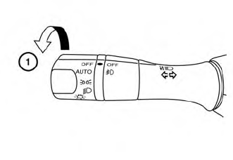
The autolight system allows the headlights to turn on and off automatically. The autolight system can:
Turn on the headlights, front parking, tail, license plate and instrument panel lights automatically when it is dark. Turn off all the lights (except daylight running lights) when it is light. Keep all the lights on for a period of time after you place the ignition switch in the OFF position and all doors are closed.