Nissan Murano: Rear Suspension :: Removal and Installation / Rear Suspension Arm
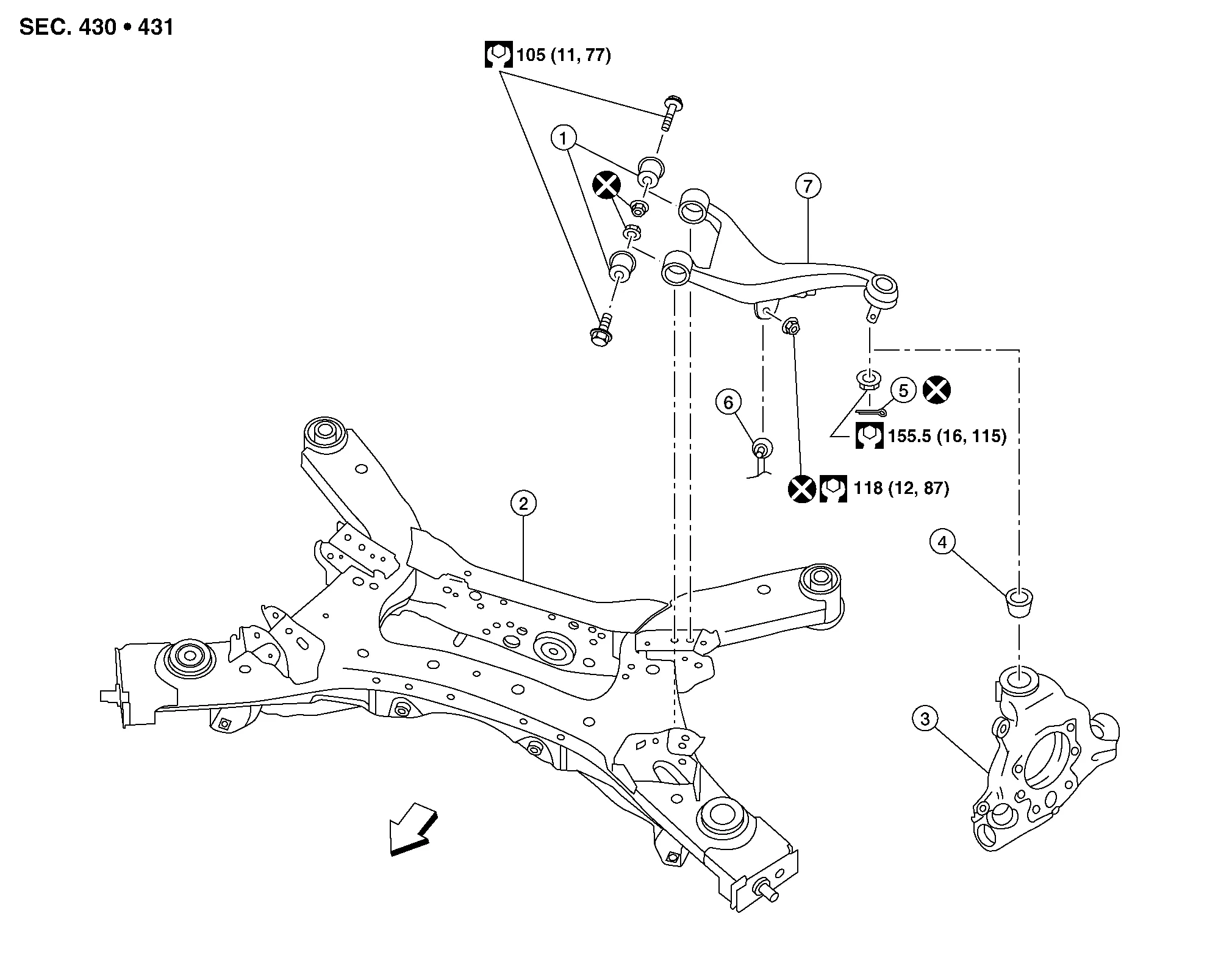
| 1. | Rear suspension arm bushing | 2. | Rear suspension member | 3. | Rear knuckle |
| 4. | Ball joint seat | 5. | Cotter pin | 6. | Stabilizer connecting rod |
| 7. | Rear suspension arm | Front |
REMOVAL
Remove the rear wheel and tire using power tool. Refer to Removal and Installation.
Support the rear lower link with a suitable jack.
WARNING:
Place a suitable jack under the outer end of the rear lower link.
CAUTION:
Do not damage the rear lower link with the suitable jack.
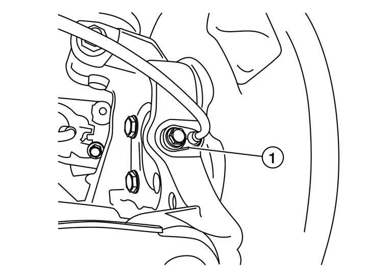
Remove bolt (1) and separate the rear wheel sensor from the knuckle. Refer to Exploded View.
CAUTION:
-
Pull out the rear wheel sensor being careful to turn it as little as possible. Do not pull on the wheel sensor harness.
-
Failure to remove the rear wheel sensor from the rear knuckle may result in damage to the rear wheel sensor.
For AWD Nissan Murano vehicles, remove the rear drive shaft. Refer to Removal and Installation.
Remove the stabilizer. Refer to Removal and Installation.
Remove the cotter pin from the rear suspension arm stud.
Remove the rear suspension arm nut from the rear knuckle using power tool. Separate the rear suspension arm from the rear knuckle.
If necessary, remove ball joint seat.
Remove the rear suspension arm nuts and bolts from the rear suspension member using power tool.
Remove the rear suspension arm.
If necessary, remove the rear suspension arm bushings.
INSPECTION AFTER REMOVAL
Ball Joint Inspection
Manually move ball joint to confirm it moves smoothly with no binding.
Swinging Torque Inspection
-
Move ball joint at least ten times by hand to check for smooth movement.
-
Hook Tool (A) on ball joint at pinch bolt location. Confirm measurement value is within specifications when ball joint begins moving.
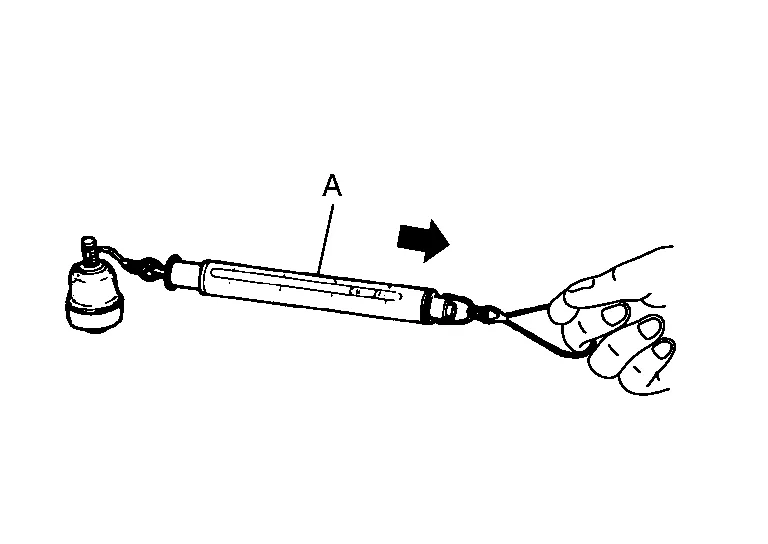
Tool number : – (J-44372) Swinging torque : Refer to Ball Joint. -
If swinging torque exceeds standard range, replace rear suspension arm.
-
Rotating Torque Inspection
-
Move ball joint at least ten times by hand to check for smooth movement.
-
Confirm measurement value is within specifications when ball joint begins rotating.
Rotating torque : Refer to Ball Joint. -
If rotating torque exceeds standard range, replace rear suspension arm.
-
Axial End Play Inspection
-
Move ball joint at least ten times by hand to check for smooth movement.
-
Move tip of ball joint in axial direction to check for looseness.
-
If there is axial end play, replace rear suspension arm.
-
INSTALLATION
Installation is in the reverse order of removal.
CAUTION:
-
Do not reuse the rear suspension arm nuts at the rear suspension member.
-
Do not reuse the cotter pin.
-
Install the rear wheel sensor to the rear knuckle. Refer to Removal and Installation.
CAUTION:
-
Before installing, make sure there is no foreign material, such as iron fragments, adhered to the pick-up part of the rear wheel sensor.
-
When installing, make sure there is no foreign material, such as iron fragments, on and in the hole in the rear knuckle for the rear wheel sensor. Make sure no foreign material has been caught in the sensor rotor. Remove any foreign material and clean the mount.
-
-
Perform the final tightening of the parts under unladen conditions with tires on level ground.
-
Check the wheel alignment. Refer to Inspection.
-
Adjust the neutral position of the steering angle sensor. Refer to Description.
-
For AWD Nissan Murano vehicles, check the rear differential gear oil level. Refer to Inspection.
 Rear Stabilizer
Exploded View
1.
Rear suspension arm
2.
Stabilizer connecting rod
3.
Stabilizer
4.
Stabilizer bushing
5.
Stabilizer clamp
Front
Removal and Installation
REMOVALRemove the rear under covers (LH/RH)...
 Rear Suspension :: Unit Removal and Installation. Rear Suspension Member
Exploded View
1.
Rear suspension member
2.
Rear suspension member stay
3.
Rear suspension member stopper
Front
Removal and Installation
REMOVALRemove the front under cover...
Other information:
Nissan Murano (Z52) 2015-2024 Service Manual: Variable Induction Air System
System Description SYSTEM DIAGRAMSYSTEM DESCRIPTIONIn the medium speed range, the ECM sends the ON signal to the VIAS control solenoid valve. This signal introduces the intake manifold vacuum into the power valve actuator and therefore closes the power valve...
Nissan Murano (Z52) 2015-2024 Service Manual: Electronic Controlled Engine Mount
System Description SYSTEM DIAGRAMSYSTEM DESCRIPTIONThe ECM controls the engine mount operation corresponding to the engine speed. The control system has a 2-step control [Soft/Hard] Vehicle condition Engine mount control Engine speed: Below 950 rpm Soft Engine speed: Above 950 rpm Hard ELECTRONIC CONTROLLED ENGINE MOUNT LINE DRAWING Electronic controlled engine mount control solenoid valve Intake manifold collector : From next figure Front electronic controlled engine mount Rear electronic controlled engine mount : To previous figure NOTE: Do not use soapy water or any type of solvent while installing vacuum hose...
Categories
- Manuals Home
- Nissan Murano Owners Manual
- Nissan Murano Service Manual
- Warning lights
- System malfunction
- Tire rotation
- New on site
- Most important about car
LATCH (Lower Anchors and Tethers for CHildren) system

LATCH system lower anchor locations - bench seat
Your vehicle is equipped with special anchor points that are used with LATCH system compatible child restraints. This system may also be referred to as the ISOFIX or ISOFIX compatible system. With this system, you do not have to use a vehicle seat belt to secure the child restraint unless the combined weight of the child and child restraint exceeds 65 lbs. (29.5 kg). If the combined weight of the child and child restraint is greater than 65 lbs. (29.5 kg), use the vehicle’s seat belt (not the lower anchors) to install the child restraint. Be sure to follow the child restraint manufacturer’s instructions for installation.