Nissan Murano: Exterior :: Removal and Installation / Front Bumper
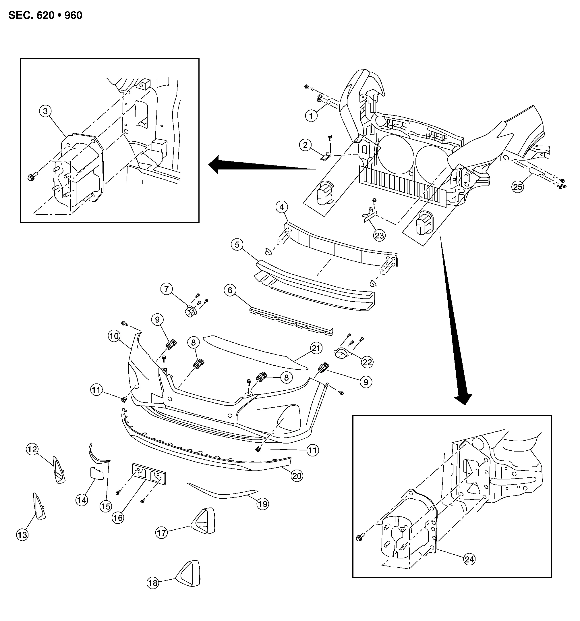
| 1. | Front bumper fascia side bracket (RH) | 2. | Front bumper side retainer (RH) | 3. | Front bumper reinforcement bracket (RH) |
| 4. | Front bumper reinforcement | 5. | Front energy absorber | 6. | Front bumper air guide |
| 7. | Front fog lamp (RH) (if equipped) | 8. | Sonar sensor (inner) | 9. | Sonar sensor (outer) |
| 10. | Front bumper fascia | 11. | Sonar finisher | 12. | Front fog lamp finisher (RH) (if equipped) |
| 13. | Front bumper fascia finisher (RH) (without fog lamp) | 14. | Tow cover | 15. | Front bumper fascia molding (RH) |
| 16. | Front license plate bracket | 17. | Front fog lamp finisher (LH) (if equipped) | 18. | Front bumper fascia finisher (LH) (without fog lamp) |
| 19. | Front bumper fascia molding (LH) | 20. | Front spoiler | 21. | Front bumper lower grille |
| 22. | Front fog lamp (LH) (if equipped) | 23. | Front bumper side retainer (LH) | 24. | Front bumper reinforcement bracket (LH) |
| 25. | Front bumper fascia side bracket (LH) |
CAUTION:
Front bumper fascia is made of resin. Use care when handling to prevent damage. Avoid contact with oily substances.
REMOVAL
Remove the front grille. Refer to Removal and Installation.
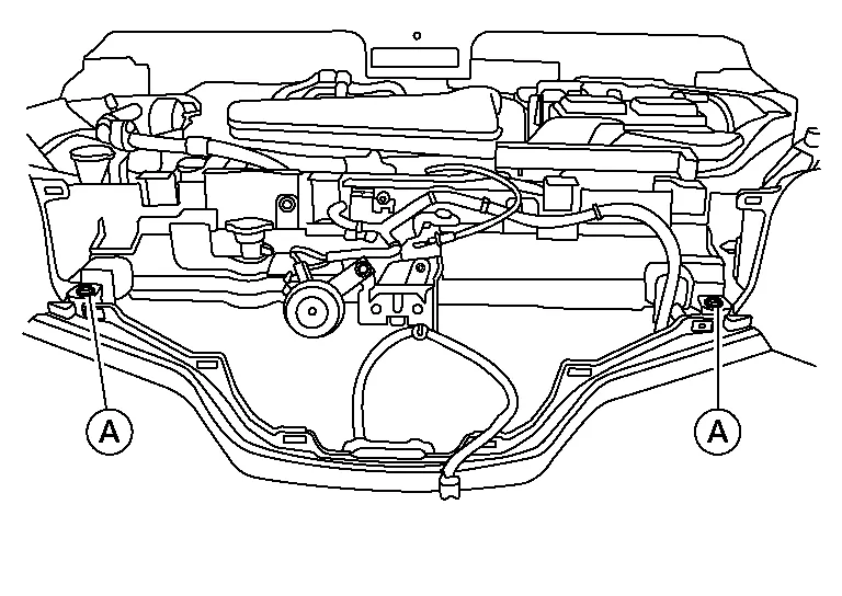
Remove the front bumper fascia clips (A).
Partially remove front over fender (LH/RH). Refer to Exploded View.
Remove engine side cover. Refer to Exploded View.
Partially remove front fender protector (LH/RH). Refer to Exploded View.
Remove front undercover (front half). Refer to Exploded View.
Remove the front bumper fascia screws (A) (LH/RH).
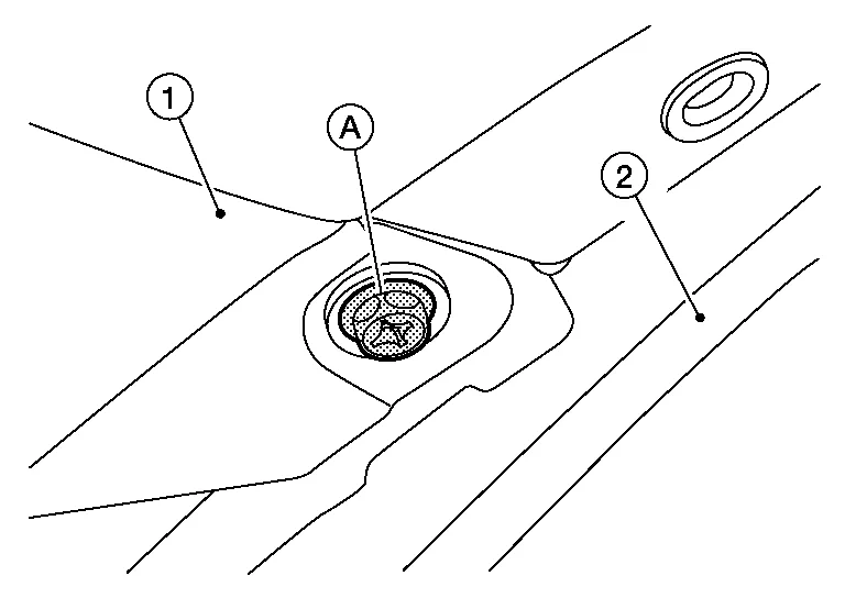
(1): Front bumper fascia
(2): Front over fender
Disconnect fog lamp harness connector (LH/RH) (if equipped).
Disconnect sonar sensor harness connectors.
Release front bumper fascia pawls from front bumper fascia side bracket (LH/RH) and remove.
CAUTION:
When removing front bumper fascia, two people are required to avoid damaging.
Remove the front energy absorber.
Remove front bumper reinforcement nuts and front bumper reinforcement.
Remove front bumper reinforcement support bolts and front bumper reinforcement support (LH/RH).
Remove front bumper side bracket bolts and the front bumper side bracket (LH/RH) (if necessary).
INSTALLATION
Installation is in the reverse order of removal.
 NOTE:
NOTE:
After installation, perform the following action test to confirm proper system operation:
-
Intelligent Cruise Control (ICC): Refer to Description.
NOTE:
-
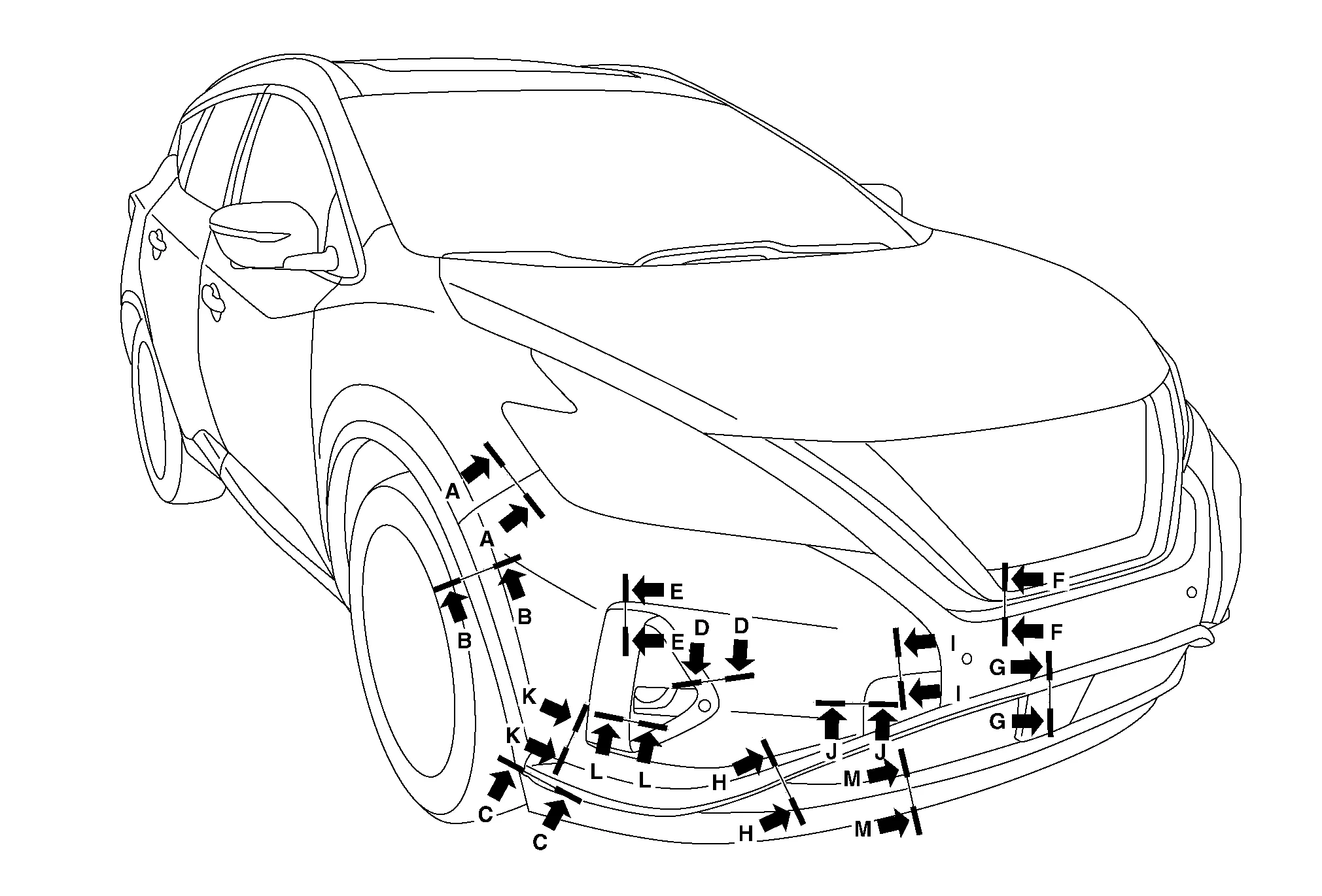
The following table shows the specified values for checking normal installation specifications.
-
Fitting adjustment cannot be performed.
| Section | Measurement | Minimum | Target Value | Maximum |
|---|---|---|---|---|
| A-A | Clearance | 0.0 (0.00) | 0.3 (0.01) | 1.0 (0.04) |
| Surface height | -0.1 (0.00) | 0.7 (0.03) | 1.5 (0.06) | |
| B-B | Clearance | 0.0 (0.00) | 0.5 (0.02) | 1.4 (0.06) |
| C-C | Clearance | 0.0 (0.00) | 0.8 (0.03) | 1.7 (0.07) |
| Surface height | -0.1 (0.00) | 0.0 (0.00) | 1.0 (0.04) | |
| D-D | Clearance | 0.0 (0.00) | 1.0 (0.04) | 2.0 (0.08) |
| E-E | Clearance | 0.0 (0.00) | 1.0 (0.04) | 2.0 (0.08) |
| F-F | Clearance | 0.2 (0.01) | 1.5 (0.06) | 2.8 (0.11) |
| G-G | Clearance | 0.4 (0.02) | 1.4 (0.06) | 2.4 (0.09) |
| H-H | Clearance | 0.5 (0.02) | 1.5 (0.06) | 2.5 (0.10) |
| I-I | Clearance | 0.0 (0.00) | 0.5 (0.02) | 1.0 (0.04) |
| Surface height | -0.2 (-0.01) | 0.3 (0.01) | 0.8 (0.03) | |
| J-J | Clearance | 0.0 (0.00) | 0.5 (0.02) | 1.0 (0.04) |
| Surface height | -0.2 (-0.01) | 0.3 (0.01) | 0.8 (0.03) | |
| K-K | Clearance | 0.0 (0.00) | 1.0 (0.04) | 2.0 (0.08) |
| L-L | Clearance | 0.3 (0.01) | 2.1 (0.08) | 3.9 (0.15) |
| M-M | Clearance | 0.0 (0.00) | 0.3 (0.01) | 1.3 (0.05) |

 Rear Bumper
Exploded View
1.
Rear bumper fascia side bracket (LH)
2.
Rear bumper fascia
3.
Rear bumper reinforcement support (LH)
4.
Rear bumper fascia reflector (LH)
5...
Other information:
Nissan Murano (Z52) 2015-2024 Service Manual: B13ec Factory Mode
DTC Description DTC DETECTION LOGIC DTC No. CONSULT screen terms (Trouble diagnosis content) DTC detection condition B13EC–52 Factory mode (AV control unit) [—] Diagnosis condition When ignition switch is ON. Signal (terminal) – Threshold – Diagnosis delay time 30 seconds or more B13EC–55 [CONFIG] Diagnosis condition When ignition switch is ON...
Nissan Murano (Z52) 2015-2024 Owners Manual: LDW system limitations
WARNING Listed below are the system limitations for the LDWsystem. Failure to follow the warnings and instructions for proper use of the LDW system could result in serious injury or death. The system will not operate at speeds below approximately 37mph(60 km/h) or if it cannot detect lane markers...
Categories
- Manuals Home
- Nissan Murano Owners Manual
- Nissan Murano Service Manual
- System malfunction
- Indicator lights
- Memory storage function (key-link)
- New on site
- Most important about car
Seatback pockets

Theremaybe one or two seatback pockets located on the back of the driver and passenger seats. The pockets can be used to store maps.
WARNING