Nissan Murano: Driveline :: Rear Propeller Shaft: C-Cvj-C / Precaution. Precautions
The Supplemental Restraint System such as “AIR BAG” and “SEAT BELT PRE-TENSIONER”, used along with a front seat belt, helps to reduce the risk or severity of injury to the driver and front passenger for certain types of collisions.
Information necessary to service the system safely is included in the “SRS AIR BAG” and “SEAT BELT” sections of this Service Manual.
WARNING:
Always observe the following items for preventing accidental activation:
-
To avoid rendering the SRS inoperative, which could increase the risk of personal injury or death in the event of a collision that would result in air bag inflation, it is recommended that all maintenance and repair be performed by an authorized NISSAN/INFINITI dealer.
-
Improper repair, including incorrect removal and installation of the SRS, can lead to personal injury caused by unintentional activation of the system. For removal of Spiral Cable and Air Bag Module, see “SRS AIR BAG”.
-
Never use electrical test equipment on any circuit related to the SRS unless instructed to in this Service Manual. SRS wiring harnesses can be identified by yellow and/or orange harnesses or harness connectors.
PRECAUTIONS WHEN USING POWER TOOLS (AIR OR ELECTRIC) AND HAMMERS
WARNING:
Always observe the following items for preventing accidental activation:
-
When working near the Air Bag Diagnosis Sensor Unit or other Air Bag System sensors with the ignition/power switch ON or engine running, never use air or electric power tools or strike near the sensor(s) with a hammer. Heavy vibration could activate the sensor(s) and deploy the air bag(s), possibly causing serious injury.
-
When using air or electric power tools or hammers, always switch the ignition/power switch OFF, disconnect the 12V battery or batteries, and wait at least 3 minutes before performing any service.
-
Replace the propeller shaft assembly if there is a breakage or deflection on tube.
-
Never hit the tube or apply an impact on it during repair service. Never damage the tube as well.
-
The joint cannot be disassembled. Never disassemble it.
-
If constant velocity joint was bent during propeller shaft assembly removal, installation, or transportation, its boot may be damaged. Wrap boot interference area to metal part with shop cloth or rubber to protect boot from breakage.

 Symptom Diagnosis. Noise, Vibration and Harshness (nvh) Troubleshooting
NVH Troubleshooting Chart
Use the chart below to find the cause of the symptom. If necessary, repair or replace these parts. Reference Inspection Exploded View Inspection Inspection Inspection Inspection Inspection NVH of REAR FINAL DRIVE in this section...
Other information:
Nissan Murano (Z52) 2015-2024 Service Manual: Diagnosis System (audio Unit)
Description The audio unit on board diagnosis performs the following functions listed in the table below: Mode Description Self Diagnosis Audio system diagnosis. Diagnoses the connections across system components. Confirmation/Adjustment Display Diagnosis The following check functions are available: Color Spectrum Bar Gradation Bar Touch Panel White Display Screenshot to USB y-curve Nissan Murano Vehicle Signals Diagnosis of signals can be performed for Vehicle Speed, Ignition, Illumination Control, MR out, Illumination Switch, Reverse, Parking Brake and ACC...
Nissan Murano (Z52) 2015-2024 Service Manual: A/c Auto Amp.
Diagnosis Procedure CHECK FUSE Check fuses [No. 14 and 29, located in the fuse block (J/B)]. NOTE: Refer to Terminal Arrangement. Is the inspection result normal? YES>> GO TO 2. NO>> Replace the blown fuse after repairing the affected circuit...
Categories
- Manuals Home
- Nissan Murano Owners Manual
- Nissan Murano Service Manual
- Rear bench seat adjustment
- Indicator lights
- Memory storage function (key-link)
- New on site
- Most important about car
Autolight system
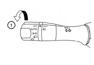
The autolight system allows the headlights to turn on and off automatically. The autolight system can:
Turn on the headlights, front parking, tail, license plate and instrument panel lights automatically when it is dark. Turn off all the lights (except daylight running lights) when it is light. Keep all the lights on for a period of time after you place the ignition switch in the OFF position and all doors are closed.