Nissan Murano: Dtc/circuit Diagnosis / P1800 Vias Control Solenoid Valve 1
DTC DETECTION LOGIC
An excessively low or high voltage signal is sent to ECM through the VIAS control solenoid valve 1.
| DTC |
CONSULT screen terms (Trouble diagnosis content) |
DTC detection condition | |
| P1800 |
VIAS S/V CIRC-B1 (VIAS solenoid valve circuit bank 1) |
Diagnosis condition | Start engine and let it idle |
| Signal (terminal) | VIAS control solenoid valve 1 signal | ||
| Threshold | An excessively low or high voltage signal is sent to ECM | ||
| Diagnosis delay time | — | ||
POSSIBLE CAUSE
-
Harness or connectors
(Input speed sensor circuit is open or shorted)
-
VIAS control solenoid valve 1
FAIL-SAFE
Not applicable
CONDITIONING
If DTC Confirmation Procedure has been previously conducted, always perform the following before conducting the next test.
-
Turn ignition switch OFF and wait at least 10 seconds.
-
Turn ignition switch ON.
-
Turn ignition switch OFF and wait at least 10 seconds.
TESTING CONDITION:
Before performing the following procedure, confirm battery voltage is more than 11 V at idle.
>>
GO TO 2.
PERFORM DTC CONFIRMATION PROCEDURE
-
Start engine and let it idle for at least 5 seconds.
-
Check 1st trip DTC.
Is 1st trip DTC detected?
YES>>Proceed to Diagnosis Procedure.
NO>>To check malfunction symptom before repair: Refer to Intermittent Incident.
NO>>Confirmation after repair: INSPECTION END
CHECK VIAS CONTROL SOLENOID VALVE 1 POWER SUPPLY
-
Turn ignition switch OFF.
-
Disconnect VIAS control solenoid valve 1 harness connector.
-
Turn ignition switch ON.
-
Check the voltage between VIAS control solenoid valve 1 harness connector and ground.
VIAS control solenoid valve 1 Ground Voltage Connector Terminal F63 1 Ground Battery voltage
Is the inspection result normal?
YES>>GO TO 2.
NO>>Repair open circuit, short to ground or short to power in harness or connectors.
CHECK VIAS CONTROL SOLENOID VALVE 1 OUTPUT SIGNAL CIRCUIT
-
Turn ignition switch OFF.
-
Disconnect ECM harness connector.
-
Check the continuity between VIAS control solenoid valve 1 harness connector and ECM harness connector.
VIAS control solenoid valve 1 ECM Continuity Connector Terminal Connector Terminal F63 2 F79 108 Existed -
Also check harness for short to ground and short to power.
Is the inspection result normal?
YES>>GO TO 3.
NO>>Repair open circuit, short to ground or short to power in harness or connectors.
CHECK VIAS CONTROL SOLENOID VALVE 1
Check VIAS control solenoid valve 1. Refer to Component Inspection.
Is the inspection result normal?
YES>>INSPECTION END
NO>>Replace VIAS control solenoid valve 1. Refer to Component Parts Location.
CHECK VIAS CONTROL SOLENOID VALVE 1
 With CONSULT
-
Turn ignition switch OFF.
-
Reconnect all harness connectors disconnected.
-
Disconnect vacuum hoses connected to VIAS control solenoid valve 1.
-
Turn ignition switch ON.
-
Select “VIAS S/V-1” in “ACTIVE TEST” mode with CONSULT.
-
Check air passage continuity and operation delay time under the following conditions.

|
Condition (VIAS S/V-1) | Air passage continuity between  and and  |
Air passage continuity between and  |
|---|---|---|
| ON | Existed | Not existed |
| OFF | Not existed | Existed |
 Without CONSULT
-
Turn ignition switch OFF.
-
Disconnect VIAS control solenoid valve 1 harness connector.
-
Disconnect vacuum hoses connected to VIAS volume control solenoid valve 1.
-
Check air passage continuity and operation delay time under the following conditions.
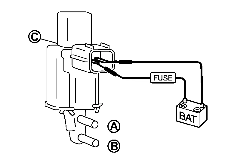
| Condition | Air passage continuity between and |
Air passage continuity between and |
|---|---|---|
| 12 V direct current supply between terminals 1 and 2 | Existed | Not existed |
| No supply | Not existed | Existed |
Is the inspection result normal?
YES>>INSPECTION END
NO>>Replace VIAS control solenoid valve 1. Refer to Component Parts Location.
 P1700 Cvt Control System
Description
This DTC is displayed with other DTC regarding TCM. Perform the trouble diagnosis for corresponding DTC. Refer to DTC Index. When this DTC is detected, the ASCD control is canceled...
 P1805 Brake Switch
DTC Description
DESCRIPTIONBrake switch signal is applied to the ECM via the stop lamp switch when the brake pedal is depressed. This signal is used mainly to decrease the engine speed when the Nissan Murano vehicle is driven...
Other information:
Nissan Murano (Z52) 2015-2024 Service Manual: B00d5 Passenger Air Bag Off Indicator
DTC Description DTC DETECTION LOGIC DTC No. CONSULT screen items (Trouble diagnosis content) DTC detecting condition B00D5-04 PASS A/B INDCTR CKT [UNIT MALFUNC] Diagnosis condition When ignition switch is ON. Signal (terminal) Front passenger air bag OFF indicator (terminal 54) Threshold — Diagnosis delay time — B00D5-15 PASS A/B INDCTR CKT [PWR-SHORT/OPEN] Diagnosis condition When ignition switch is ON...
Nissan Murano (Z52) 2015-2024 Service Manual: Main Line Between Hvac and 4wd Circuit
Diagnosis Procedure CHECK CONNECTOR Turn the ignition switch OFF. Disconnect the battery cable from the negative terminal. Check the following terminals and connectors for damage, bend and loose connection (connector side and harness side). Harness connector M84 Harness connector B101 Is the inspection result normal? YES>> GO TO 2...
Categories
- Manuals Home
- Nissan Murano Owners Manual
- Nissan Murano Service Manual
- Passenger compartment
- High Beam Assist (if so equipped)
- All-Wheel Drive (AWD) (if so equipped)
- New on site
- Most important about car
Front manual seat adjustment (if so equipped)
Your vehicle seats can be adjusted manually. For additional information about adjusting the seats, refer to the steps outlined in this section.
Forward and backward
