
Nissan Murano: Dtc/circuit Diagnosis / P0863 Tcm Communication
DTC DETECTION LOGIC
| DTC |
CONSULT screen terms (Trouble diagnosis content) |
DTC detection condition | |
| P0863 |
CONTROL UNIT (CAN) (TCM Communication Circuit) |
Diagnosis condition | Engine is started |
| Signal | — | ||
| Threshold | An error is detected at the initial CAN diagnosis of TCM | ||
| Diagnosis delay time | Within 1 second | ||
POSSIBLE CAUSE
TCM
FAIL-SAFE
-
Selector shock is large
-
Start is slow
-
Acceleration is slow
-
Lock-up is not performed
PREPARATION BEFORE WORK
If another "DTC CONFIRMATION PROCEDURE" occurs just before, turn ignition switch OFF and wait for at least 10 seconds, then perform the next test.
>>
GO TO 2.
CHECK DTC DETECTION
-
Start the engine.
-
Check the DTC.
Is “P0863” detected?
YES>>Go to Diagnosis Procedure.
NO-1>>To check malfunction symptom before repair: Refer to Intermittent Incident.
NO-2>>Confirmation after repair: INSPECTION END
CHECK INTERMITTENT INCIDNT
Refer to Intermittent Incident.
Is the inspection result normal?
YES>>Replace TCM. Refer to Removal and Installation.
NO>>Repair or replace malfunctioning parts.
 P0847 Transmission Fluid Pressure Sen/sw B
DTC Description
DTC DETECTION LOGIC DTC
CONSULT screen terms
(Trouble diagnosis content)
DTC detection condition
P0847
FLUID PRESS SEN/SW B
(Transmission Fluid Pressure Sensor/Switch B Circuit Low)
Diagnosis condition
When all of the following conditions are satisfied:
CVT fluid temperature: More than −20°C (−4°F)
TCM power supply voltage: 11 V or more
Signal
—
Threshold
Secondary pressure sensor voltage: 0...
 P0890 Tcm
DTC Description
DTC DETECTION LOGIC DTC
CONSULT screen terms
(Trouble diagnosis content)
DTC detection condition
P0890
TCM
(Transmission Control Module Power Relay Sense Circuit Low)
Diagnosis condition
TCM power supply voltage: More than 11 V
Signal
—
Threshold
Battery voltage: Less than 8...
Other information:
Nissan Murano (Z52) 2015-2024 Service Manual: Motion Activated Back Door Control Unit
Reference Value TERMINAL LAYOUTPHYSICAL VALUES Terminal No. (Wire color) Description Condition Voltage (Approx.) (+) (–) Signal name Input/Output 1 (L) Ground Serial communication Input/Output — — 2 (V) Ground Power supply (BAT) Input — Battery voltage 3 (B) Ground Ground — — 0 V 4 (W) Ground Motion activated back door sensor (upper) input signal Input — — 5 (W) Ground Motion activated back door sensor (upper) output signal Input — — 6 (W) Ground Motion activated back door sensor (lower) input signal Input — — 7 (W) Ground Motion activated back door sensor (lower) output signal Input — — NOTE: Voltage generated in communication circuit between motion activated back door sensor and motion activated back door control unit is extremely low and therefore cannot be measured...
Nissan Murano (Z52) 2015-2024 Service Manual: Internal Heat Exchanger
Removal and Installation REMOVALDischarge the refrigerant. Refer to Recycle Refrigerant. Remove the engine room cover. Refer to Removal and Installation. Remove the torque member bolts. Refer to Exploded View. Position the brake caliper assembly aside using wire...
Categories
- Manuals Home
- Nissan Murano Owners Manual
- Nissan Murano Service Manual
- Turning the AEB system on/off
- Indicator lights
- Fuel recommendation
- New on site
- Most important about car
Unfastening the seat belts. Checking seat belt operation
Unfastening the seat belts
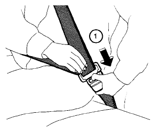
To unfasten the seat belt, press the button
on the buckle  . The seat belt
automatically
retracts.
