Nissan Murano: Dtc/circuit Diagnosis / P0171 Fuel Injection System Function
DTC DETECTION LOGIC
With the Air/Fuel Mixture Ratio Self-Learning Control, the actual mixture ratio can be brought closely to the theoretical mixture ratio based on the mixture ratio feedback signal from A/F sensor 1. The ECM calculates the necessary compensation to correct the offset between the actual and the theoretical ratios.
In case the amount of the compensation value is extremely large (the actual mixture ratio is too lean), the ECM judges the condition as the fuel injection system malfunction and illuminates the MIL (2 trip detection logic).
| Sensor | Input signal to ECM | ECM function | Actuator |
|---|---|---|---|
| A/F sensor 1 |
Density of oxygen in exhaust gas (Mixture ratio feedback signal) |
Fuel injection control | Fuel injector |
-
Fuel injection system does not operate properly.
-
The amount of mixture ratio compensation is too large. (The mixture ratio is too lean.)
| DTC |
CONSULT screen terms (Trouble diagnosis content) |
DTC detection condition | ||
| P0171 |
FUEL SYS-LEAN-B1 (System too lean bank 1) |
1 | Diagnosis condition |
|
| Signal (terminal) | — | |||
| Threshold | Fuel injection system does not operate properly. | |||
| Diagnosis delay time | — | |||
| 2 | Diagnosis condition |
|
||
| Signal (terminal) | — | |||
| Threshold | The amount of mixture ratio compensation is too large. (The mixture ratio is too lean.) | |||
| Diagnosis delay time | — | |||
| P0174 |
FUEL SYS-LEAN-B2 (System too lean bank 2) |
1 | Diagnosis condition |
|
| Signal (terminal) | — | |||
| Threshold | Fuel injection system does not operate properly. | |||
| Diagnosis delay time | — | |||
| 2 | Diagnosis condition |
|
||
| Signal (terminal) | — | |||
| Threshold | The amount of mixture ratio compensation is too large. (The mixture ratio is too lean.) | |||
| Diagnosis delay time | — | |||
POSSIBLE CAUSE
P0171
-
Intake air leakage
-
A/F sensor 1
-
Fuel injector
-
Exhaust gas leakage
-
Incorrect fuel pressure
-
Lack of fuel
-
Mass air flow sensor
-
Incorrect PCV hose connection
P0174
-
Intake air leakage
-
A/F sensor 1
-
Fuel injector
-
Exhaust gas leakage
-
Incorrect fuel pressure
-
Lack of fuel
-
Mass air flow sensor
-
Incorrect PCV hose connection
FAIL-SAFE
Not applicable
PRECONDITIONING
If DTC Confirmation Procedure has been previously conducted, always perform the following before conducting the next test.
-
Turn ignition switch OFF and wait at least 10 seconds.
-
Turn ignition switch ON.
-
Turn ignition switch OFF and wait at least 10 seconds.
>>
GO TO 2.
PERFORM DTC CONFIRMATION PROCEDURE-I
-
Clear the mixture ratio self-learning value. Refer to Description.
-
Start engine.
Is it difficult to start engine?
YES>>GO TO 3.
NO>>GO TO 4.
RESTART ENGINE
If it is difficult to start engine, the fuel injection system has a malfunction, too.
Crank engine while depressing accelerator pedal.
 NOTE:
NOTE:
-
When depressing accelerator pedal three-fourths (3/4) or more, the control system does not start the engine. Do not depress accelerator pedal too much.
Does engine start?
YES>>Proceed to Diagnosis Procedure.
NO>>Check exhaust and intake air leakage visually.
PERFORM DTC CONFIRMATION PROCEDURE-II
-
Keep engine idle for at least 5 minutes.
-
Check 1st trip DTC.
Is 1st trip DTC detected?
YES>>Proceed to Diagnosis Procedure.
NO>>GO TO 5.
PERFORM DTC CONFIRMATION PROCEDURE-III
-
Turn ignition switch OFF and wait at least 10 seconds.
-
Start engine.
-
Maintain the following conditions for at least 10 consecutive minutes.
Hold the accelerator pedal as steady as possible.
VHCL SPEED SE 50 - 120 km/h (31 - 75 mph) CAUTION:
Always drive Nissan Murano vehicle at a safe speed.
-
Check 1st trip DTC.
Is 1st trip DTC detected?
YES>>Proceed to Diagnosis Procedure.
NO>>To check malfunction symptom before repair: Refer to Intermittent Incident.
NO>>Confirmation after repair: INSPECTION END
CHECK EXHAUST GAS LEAKAGE
-
Start engine and run it at idle.
-
Listen for an exhaust gas leakage before three way catalyst (manifold).
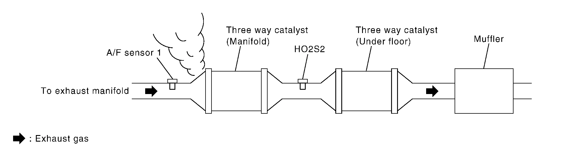
Is exhaust gas leakage detected?
YES>>Repair or replace malfunctioning part.
NO>>GO TO 2.
CHECK FOR INTAKE AIR LEAKAGE
-
Listen for an intake air leakage after the mass air flow sensor.
-
Check PCV hose connection.
Is intake air leakage detected?
YES>>Repair or replace malfunctioning part.
NO>>GO TO 3.
CHECK A/F SENSOR 1 INPUT SIGNAL CIRCUIT
-
Turn ignition switch OFF.
-
Disconnect corresponding A/F sensor 1 harness connector.
-
Disconnect ECM harness connector.
-
Check the continuity between A/F sensor 1 harness connector and ECM harness connector.
DTC A/F sensor 1 ECM Continuity Bank Connector Terminal Connector Terminal P0171 1 F12 3 F79 66 Existed 4 67 P0174 2 F61 3 76 4 77 -
Check the continuity between A/F sensor 1 harness connector and ground, or ECM harness connector and ground.
DTC A/F sensor 1 Ground Continuity Bank Connector Terminal P0171 1 F12 3 Ground Not existed 4 P0174 2 F61 3 4 DTC ECM Ground Continuity Connector Terminal P0171 F79 66 Ground Not existed 67 P0174 76 77 -
Also check harness for short to power.
Is the inspection result normal?
YES>>GO TO 4.
NO>>Repair open circuit, short to ground or short to power in harness or connectors.
CHECK A/F SENSOR 1 FUNCTION CHECK-1
If DTC Confirmation Procedure has been previously conducted, always perform the following before conducting the next test.
-
Turn ignition switch OFF and wait at least 10 seconds.
-
Turn ignition switch ON.
-
Turn ignition switch OFF and wait at least 10 seconds.
TESTING CONDITION:
Before performing the following procedure, confirm that battery voltage is more than 11 V at idle.
>>
GO TO 5.
CHECK A/F SENSOR 1 FUNCTION CHECK-2
-
Clear the mixture ratio self-learning value. Refer to Description.
-
Turn ignition switch OFF and wait at least 10 seconds.
-
Turn ignition switch ON.
-
Turn ignition switch OFF and wait at least 10 seconds.
-
Start engine and keep the engine speed between 3,500 and 4,000 rpm for 1 minute under no load.
-
Let engine idle for 1 minute.
-
Keep engine speed between 2,500 and 3,000 rpm for 20 minutes.
-
Check DTC.
Is DTC detected?
YES>>Replace A/F sensor. Refer to Exploded View.
NO>>GO TO 6.
CHECK FUEL PRESSURE
Check fuel pressure. Refer to Work Procedure.
Is the inspection result normal?
YES>>GO TO 8.
NO>>GO TO 7.
DETECT MALFUNCTIONING PART
Check fuel hoses and fuel tubes for clogging.
Is the inspection result normal?
YES>>Replace “fuel filter and fuel pump assembly”. Refer to Removal and Installation.
NO>>Repair or replace malfunctioning part.
CHECK MASS AIR FLOW SENSOR
 With CONSULT
-
Install all removed parts.
-
Check “MASS AIR FLOW” in “DATA MONITOR” mode with CONSULT.
For specification, refer to Component Inspection.
 With GST
-
Install all removed parts.
-
Check mass air flow sensor signal in Service $01 with GST.
For specification, refer to Mass Air Flow Sensor.
Is the measurement value within the specification?
YES>>GO TO 9.
NO>>Check connectors for rusted terminals or loose connections in the mass air flow sensor circuit or ground. Refer to Diagnosis Procedure.
CHECK FUNCTION OF FUEL INJECTOR
With CONSULT
-
Start engine.
-
Perform “POWER BALANCE” in “ACTIVE TEST” mode with CONSULT.
-
Check that each circuit produces a momentary engine speed drop.
With GST
-
Let engine idle.
-
Listen to each fuel injector operating sound.
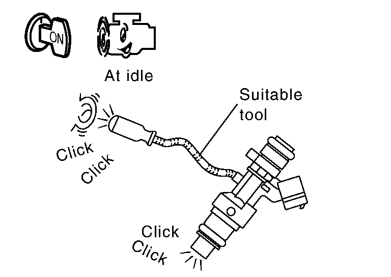
Is the inspection result normal?
YES>>GO TO 10.
NO>>Perform trouble diagnosis for FUEL INJECTOR, refer to Diagnosis Procedure.
CHECK FUEL INJECTOR
-
Turn ignition switch OFF.
-
Confirm that the engine is cooled down and there are no fire hazards near the Nissan Murano vehicle.
-
Disconnect all fuel injector harness connectors.
-
Remove fuel tube assembly. Refer to Removal and Installation.
Keep fuel hose and all fuel injectors connected to fuel tube.
-
For DTC P0171, reconnect fuel injector harness connectors on bank 1.
For DTC P0174, reconnect fuel injector harness connectors on bank 2.
-
Disconnect all ignition coil harness connectors.
-
Prepare pans or saucers under each fuel injector.
-
Crank engine for about 3 seconds.
For DTC P0171, check that fuel sprays out from fuel injectors on bank 1.
For DTC P0174, check that fuel sprays out from fuel injectors on bank 2.
Fuel should be sprayed evenly for each fuel injector.
Is the inspection result normal?
YES>>INSPECTION END
NO>>Replace fuel injectors from which fuel does not spray out. Always replace O-ring with new ones. Refer to Removal and Installation.
 P014c A/f Sensor 1
DTC Description
DTC DETECTION LOGICTo judge malfunctions, this diagnosis measures response time of the A/F signal computed by ECM from the A/F sensor 1 signal...
 P0181 Ftt Sensor
DTC Description
DTC DETECTION LOGIC
Rationally incorrect voltage from the sensor is sent to ECM, compared with the voltage signals from ECT sensor and intake air temperature sensor...
Other information:
Nissan Murano (Z52) 2015-2024 Service Manual: Back Door Side Finisher
Removal and Installation REMOVALRemove back door upper finisher. Refer to Removal and Installation. Remove back door lower finisher. Refer to Removal and Installation. Release back door side finisher metal clips using a suitable tool then remove back door side finisher...
Nissan Murano (Z52) 2015-2024 Service Manual: Air Mix Door Motor Lh
Diagnosis Procedure CHECK AIR MIX DOOR MOTOR LH POWER SUPPLY Ignition switch ON. Check voltage between air mix door motor LH harness connector and ground. + − Voltage (Approx.) Air mix door motor LH Connector Terminal M155 1 Ground Battery voltage Is the inspection result normal? YES>> GO TO 2...
Categories
- Manuals Home
- Nissan Murano Owners Manual
- Nissan Murano Service Manual
- Turning the AEB system on/off
- System malfunction
- Warning lights
- New on site
- Most important about car
Seatback pockets

Theremaybe one or two seatback pockets located on the back of the driver and passenger seats. The pockets can be used to store maps.
WARNING