Nissan Murano: Dtc/circuit Diagnosis / P014c A/f Sensor 1
DTC DETECTION LOGIC
To judge malfunctions, this diagnosis measures response time of the A/F signal computed by ECM from the A/F sensor 1 signal. The time is compensated by engine operating (speed and load), fuel feedback control constant, and the A/F sensor 1 temperature index. Judgment is based on whether the compensated time (the A/F signal cycling time index) is inordinately long or not.
The response time of a A/F sensor 1 signal delays more than the specified time computed by ECM.
| DTC |
CONSULT screen terms (Trouble diagnosis content) |
DTC detection condition | |
| P014C |
A/F SENSOR1 (B1) (O2 sensor slow response - rich to lean bank 1 sensor 1) |
Diagnosis condition | — |
| Signal (terminal) | A/F sensor 1 signal | ||
| Threshold | The response time of a A/F sensor 1 signal delays more than the specified time computed by ECM | ||
| Diagnosis delay time | — | ||
| P014D |
A/F SENSOR1 (B1) (O2 sensor slow response - lean to rich bank 1 sensor 1) |
Diagnosis condition | — |
| Signal (terminal) | A/F sensor 1 signal | ||
| Threshold | The response time of a A/F sensor 1 signal delays more than the specified time computed by ECM | ||
| Diagnosis delay time | — | ||
| P014E |
A/F SENSOR1 (B2) (O2 sensor slow response - rich to lean bank 2 sensor 1) |
Diagnosis condition | — |
| Signal (terminal) | A/F sensor 1 signal | ||
| Threshold | The response time of a A/F sensor 1 signal delays more than the specified time computed by ECM | ||
| Diagnosis delay time | — | ||
| P014F |
A/F SENSOR1 (B2) (O2 sensor slow response - lean to rich bank 2 sensor 1) |
Diagnosis condition | — |
| Signal (terminal) | A/F sensor 1 signal | ||
| Threshold | The response time of a A/F sensor 1 signal delays more than the specified time computed by ECM | ||
| Diagnosis delay time | — | ||
| P015A |
A/F SENSOR1 (B1) (O2 sensor delayed response - rich to lean bank 1 sensor 1) |
Diagnosis condition | — |
| Signal (terminal) | A/F sensor 1 signal | ||
| Threshold | The response time of a A/F sensor 1 signal delays more than the specified time computed by ECM | ||
| Diagnosis delay time | — | ||
| P015B |
A/F SENSOR1 (B1) (O2 sensor delayed response - lean to rich bank 1 sensor 1) |
Diagnosis condition | — |
| Signal (terminal) | A/F sensor 1 signal | ||
| Threshold | The response time of a A/F sensor 1 signal delays more than the specified time computed by ECM | ||
| Diagnosis delay time | — | ||
| P015C |
A/F SENSOR1 (B2) (O2 sensor delayed response - rich to lean bank 2 sensor 1) |
Diagnosis condition | — |
| Signal (terminal) | A/F sensor 1 signal | ||
| Threshold | The response time of a A/F sensor 1 signal delays more than the specified time computed by ECM | ||
| Diagnosis delay time | — | ||
| P015D |
A/F SENSOR1 (B2) (O2 sensor delayed response - lean to rich bank 2 sensor 1) |
Diagnosis condition | — |
| Signal (terminal) | A/F sensor 1 signal | ||
| Threshold | The response time of a A/F sensor 1 signal delays more than the specified time computed by ECM | ||
| Diagnosis delay time | — | ||
POSSIBLE CAUSE
P014C
-
Harness or connectors (The A/F sensor 1 circuit is open or shorted.)
-
A/F sensor 1
P014D
-
Harness or connectors (The A/F sensor 1 circuit is open or shorted.)
-
A/F sensor 1
P014E
-
Harness or connectors (The A/F sensor 1 circuit is open or shorted.)
-
A/F sensor 1
P014F
-
Harness or connectors (The A/F sensor 1 circuit is open or shorted.)
-
A/F sensor 1
P015A
-
Harness or connectors (The A/F sensor 1 circuit is open or shorted.)
-
A/F sensor 1
P015B
-
Harness or connectors (The A/F sensor 1 circuit is open or shorted.)
-
A/F sensor 1
P015C
-
Harness or connectors (The A/F sensor 1 circuit is open or shorted.)
-
A/F sensor 1
P015D
-
Harness or connectors (The A/F sensor 1 circuit is open or shorted.)
-
A/F sensor 1
FAIL-SAFE
Not applicable
PRECONDITIONING
If DTC Confirmation Procedure has been previously conducted, always perform the following procedure before conducting the next test.
-
Turn ignition switch OFF and wait at least 10 seconds.
-
Turn ignition switch ON.
-
Turn ignition switch OFF and wait at least 10 seconds.
TESTING CONDITION:
Before performing the following procedure, confirm that battery voltage is more than 11 V at idle.
Do you have CONSULT?
YES>>GO TO 2.
NO>>GO TO 6.
PERFORM DTC CONFIRMATION PROCEDURE-1
 With CONSULT
-
Start engine and warm it up to normal operating temperature.
-
Turn ignition switch OFF and wait at least 10 seconds.
-
Turn ignition switch ON.
-
Turn ignition switch OFF and wait at least 10 seconds.
-
Start engine and keep the engine speed between 3,500 and 4,000 rpm for at least 1minute under no load.
-
Let engine idle for 1 minute.
-
Increase the engine speed up to about 3,600 rpm and keep it for 10 seconds.
-
Fully release accelerator pedal and then let engine idle for about 1 minute.
-
Check the items status of “DATA MONITOR” as follows.
 NOTE:
NOTE:
If “PRSNT” changed to “ABSNT”, refer to Component Function Check.
DTC Data monitor item Status -
P014C
-
P014D
-
P015A
-
P015B
A/F SEN1 DIAG3 (B1) PRSNT -
P014E
-
P014F
-
P015C
-
P015D
A/F SEN1 DIAG3 (B2) -
Is “PRSNT” displayed on CONSULT screen?
YES>>GO TO 4.
NO>>GO TO 3.
PERFORM DTC CONFIRMATION PROCEDURE-2
With CONSULT
Perform DTC confirmation procedure-1 again.
Is “PRSNT” displayed on CONSULT screen?
YES>>GO TO 4.
NO>>Refer to Component Function Check.
PERFORM DTC CONFIRMATION PROCEDURE-2
With CONSULT
-
Wait for about 20 seconds at idle.
-
Check the items status of “DATA MONITOR” as follows.
NOTE:
If “CMPLT” changed to “INCMP”, refer to Component Function Check.
DTC Data monitor item Status -
P014C
-
P014D
-
P015A
-
P015B
A/F SEN1 DIAG1 (B1) CMPLT A/F SEN1 DIAG2 (B1) -
P014E
-
P014F
-
P015C
-
P015D
A/F SEN1 DIAG1 (B2) A/F SEN1 DIAG2 (B2) -
Is “CMPLT” displayed on CONSULT screen?
YES>>GO TO 5.
NO>>Refer to Component Function Check.
PERFORM SELF-DIAGNOSIS
With CONSULT
Check the “SELF-DIAG RESULT”.
Is any DTC detected?
YES>>Proceed to Diagnosis Procedure.
NO>>To check malfunction symptom before repair: Refer to Intermittent Incident.
NO>>Confirmation after repair: INSPECTION END
CHECK AIR-FUEL RATIO SELF-LEARNING VALUE
 With GST
-
Start engine and warm it up to normal operating temperature.
-
Select Service $01 with GST.
-
Calculate the total value of “Short term fuel trim” and “Long term fuel trim” indications.
Is the total percentage within ±15%?
YES>>GO TO 8.
NO>>GO TO 7.
DETECT MALFUNCTIONING PART
Check the following.
-
Intake air leaks
-
Exhaust gas leaks
-
Incorrect fuel pressure
-
Lack of fuel
-
Fuel injector
-
Incorrect PCV hose connection
-
PCV valve
-
Mass air flow sensor
>>
Repair or replace malfunctioning part.
PERFORM DTC CONFIRMATION PROCEDURE
-
Turn ignition switch OFF and wait at least 10 seconds.
-
Turn ignition switch ON.
-
Turn ignition switch OFF and wait at least 10 seconds.
-
Start engine and keep the engine speed between 3,500 and 4,000 rpm for at least 1 minute under no load.
-
Let engine idle for 1 minute.
-
Increase the engine speed up to about 3,600 rpm and keep it for 10 seconds.
-
Fully release accelerator pedal and then let engine idle for about 1 minute.
-
Check 1st trip DTC.
Is 1st trip DTC detected?
YES>>Proceed to Diagnosis Procedure.
NO>>To check malfunction symptom before repair: Refer to Intermittent Incident.
NO>>Confirmation after repair: INSPECTION END
RETIGHTEN A/F SENSOR 1
Loosen and retighten the A/F sensor 1. Refer to Removal and Installation (bank 2), Removal and Installation (bank 1).
>>
GO TO 2.
CHECK EXHAUST GAS LEAK
-
Start engine and run it at idle.
-
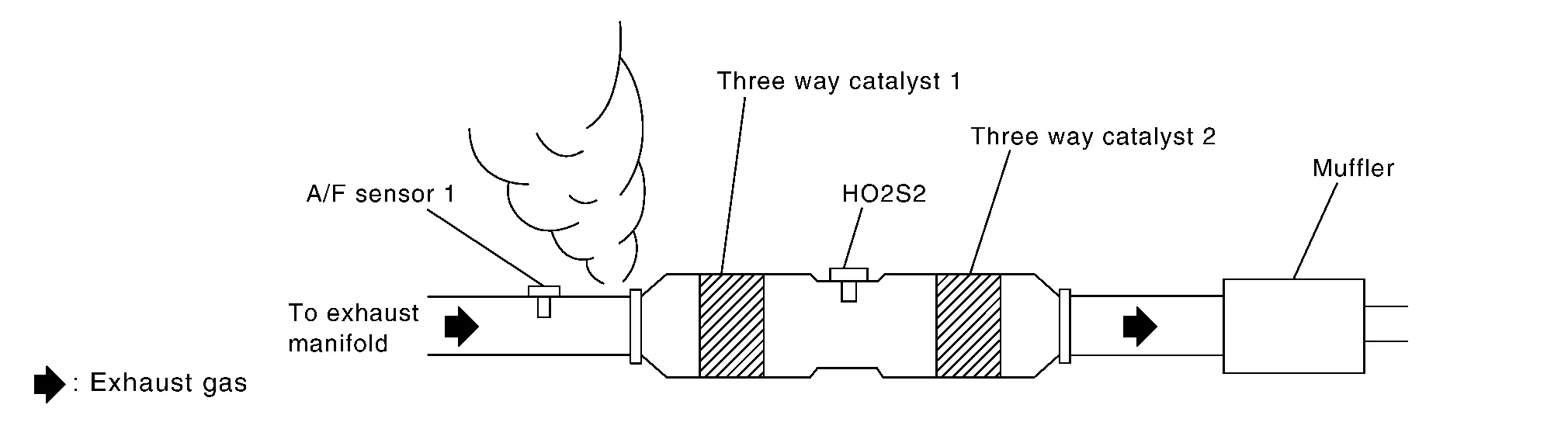
Listen for an exhaust gas leak before three way catalyst 1.
Is exhaust gas leak detected?
YES>>Repair or replace.
NO>>GO TO 3.
CHECK FOR INTAKE AIR LEAK
Listen for an intake air leak after the mass air flow sensor.
Is intake air leak detected?
YES>>Repair or replace.
NO>>GO TO 4.
CLEAR THE MIXTURE RATIO SELF-LEARNING VALUE
-
Clear the mixture ratio self-learning value. Refer to Description.
-
Run engine for at least 10 minutes at idle speed.
Is the 1st trip DTC P0171, P0172, P0174 or P0175 detected? Is it difficult to start engine?
YES>>Perform trouble diagnosis for DTC P0171, P0174 or P0172, P0175. Refer to DTC Description or DTC Description.
NO>>GO TO 5.
CHECK AIR FUEL RATIO (A/F) SENSOR 1 POWER SUPPLY
-
Disconnect A/F sensor 1 harness connector.
-
Turn ignition switch ON.
-
Check the voltage between A/F sensor 1 harness connector and ground.
DTC A/F sensor 1 Ground Voltage Bank Connector Terminal -
P014C
-
P014D
-
P015A
-
P015B
1 F12 1 Ground Battery voltage -
P014E
-
P014F
-
P015C
-
P015D
2 F61 1 -
Is the inspection result normal?
YES>>GO TO 7.
NO>>GO TO 6.
CHECK AIR FUEL RATIO (A/F) SENSOR 1 POWER SUPPLY CIRCUIT
-
Turn ignition switch OFF.
-
Disconnect IPDM E/R harness connector.
-
Check the continuity between A/F sensor 1 harness connector and IPDM E/R harness connector.
| DTC | A/F sensor 1 | IPDM E/R | Continuity | |||
|---|---|---|---|---|---|---|
| Bank | Connector | Terminal | Connector | Terminal | ||
|
1 | F12 | 1 | F19 | 52 | Existed |
|
2 | F61 | 1 | 53 | ||
Is the inspection result normal?
YES>>Perform the trouble diagnosis for power supply circuit.
NO>>Repair or replace error-detected parts.
CHECK A/F SENSOR 1 INPUT SIGNAL CIRCUIT FOR OPEN AND SHORT
-
Turn ignition switch OFF.
-
Disconnect ECM harness connector.
-
Check the continuity between A/F sensor 1 harness connector and ECM harness connector.
DTC A/F sensor 1 ECM Continuity Bank Connector Terminal Connector Terminal -
P014C
-
P014D
-
P015A
-
P015B
1 F12 3 F79 66 Existed 4 67 -
P014E
-
P014F
-
P015C
-
P015D
2 F61 3 76 4 77 -
-
Check the continuity between A/F sensor 1 harness connector and ground, or ECM harness connector and ground.
DTC A/F sensor 1 Ground Continuity Bank Connector Terminal -
P014C
-
P014D
-
P015A
-
P015B
1 F12 3 Ground Not existed 4 -
P014E
-
P014F
-
P015C
-
P015D
2 F61 3 4 DTC ECM Ground Continuity Bank Connector Terminal -
P014C
-
P014D
-
P015A
-
P015B
1 F79 66 Ground Not existed 67 -
P014E
-
P014F
-
P015C
-
P015D
2 76 77 -
-
Also check harness for short to power.
Is the inspection result normal?
YES>>GO TO 8.
NO>>Repair open circuit, short to ground or short to power in harness or connectors.
CHECK AIR FUEL RATIO (A/F) SENSOR 1 HEATER
Check air fuel ratio (A/F) sensor 1 heater. Refer to Component Inspection.
Is the inspection result normal?
YES>>GO TO 9.
NO>>Replace malfunctioning air fuel ratio (A/F) sensor 1. Refer to Removal and Installation (bank 2), Removal and Installation (bank 1).
CHECK MASS AIR FLOW SENSOR
Check both mass air flow sensor (bank 1 and bank 2). Refer to Component Inspection.
Is the inspection result normal?
YES>>GO TO 10.
NO>>Replace malfunctioning mass air flow sensor. Refer to Removal and Installation.
CHECK PCV VALVE
Check PCV valve. Refer to Work Procedure.
Is the inspection result normal?
YES>>INSPECTION END
NO>>Repair or replace PCV valve. Refer to Component Parts Location.
 P0139 Ho2s2
DTC Description
DTC DETECTION LOGICThe heated oxygen sensor 2 has a much longer switching time between rich and lean than the air fuel ratio (A/F) sensor 1...
 P0171 Fuel Injection System Function
DTC Description
DTC DETECTION LOGICWith the Air/Fuel Mixture Ratio Self-Learning Control, the actual mixture ratio can be brought closely to the theoretical mixture ratio based on the mixture ratio feedback signal from A/F sensor 1...
Other information:
Nissan Murano (Z52) 2015-2024 Service Manual: System. Charging System
System Description SYSTEM DIAGRAMSignal transmission function list Component Signal Combination meter Charge warning lamp signal System DescriptionThe generator provides DC voltage to operate the vehicle's electrical system and to keep the battery charged...
Nissan Murano (Z52) 2015-2024 Owners Manual: NISSAN Vehicle Immobilizer System keys
You can only drive your vehicle using the Intelligent Keys which are registered to the NISSAN Vehicle Immobilizer System components in your vehicle. The mechanical key can be used for all the locks. Never leave the keys in the vehicle. Additional or replacement keys: If you still have a key, the key number is not necessary when you need extra NISSAN Vehicle Immobilizer System keys...
Categories
- Manuals Home
- Nissan Murano Owners Manual
- Nissan Murano Service Manual
- Settings
- Turning the AEB system on/off
- Warning lights
- New on site
- Most important about car
Driver and passenger supplemental knee air bag

Driver’s side
The knee air bag is located in the knee bolster, on the driver’s and passenger’s side. All of the information, cautions and warnings in this manual apply and must be followed. The knee air bag is designed to inflate in higher severity frontal collisions, although it may inflate if the forces in another type of collision are similar to those of a higher severity frontal impact. It may not inflate in certain collisions.

Passenger’s side