Nissan Murano: Dtc/circuit Diagnosis / P0078 Evt Control Solenoid Valve
DTC DETECTION LOGIC
An improper voltage is sent to the ECM through exhaust valve timing control solenoid valve.
| DTC |
CONSULT screen terms (Trouble diagnosis content) |
DTC detection condition | |
| P0078 |
EX V/T ACT/CIRC-B1 [Exhaust valve timing control solenoid valve (bank 1) circuit] |
Diagnosis condition | Start engine and let it idle |
| Signal (terminal) | Voltage signal transmitted from exhaust valve timing control solenoid valve to ECM | ||
| Threshold | An improper voltage is sent to the ECM through exhaust valve timing control solenoid valve | ||
| Diagnosis delay time | — | ||
| P0084 |
EX V/T ACT/CIRC-B2 [Exhaust valve timing control solenoid valve (bank 2) circuit] |
Diagnosis condition | Start engine and let it idle |
| Signal (terminal) | Voltage signal transmitted from exhaust valve timing control solenoid valve to ECM | ||
| Threshold | An improper voltage is sent to the ECM through exhaust valve timing control solenoid valve | ||
| Diagnosis delay time | — | ||
POSSIBLE CAUSE
P0078
-
Harness or connectors (Exhaust valve timing control solenoid valve circuit is open or shorted.)
-
Exhaust valve timing control solenoid valve
P0084
-
Harness or connectors (Exhaust valve timing control solenoid valve circuit is open or shorted.)
-
Exhaust valve timing control solenoid valve
FAIL-SAFE
Not applicable
PRECONDITIONING
If DTC Confirmation Procedure has been previously conducted, always perform the following procedure before conducting the next test.
-
Turn ignition switch OFF and wait at least 10 seconds.
-
Turn ignition switch ON.
-
Turn ignition switch OFF and wait at least 10 seconds.
>>
GO TO 2.
PERFORM DTC CONFIRMATION PROCEDURE
-
Start the engine and let it idle for 5 seconds.
-
Check 1st trip DTC.
Is 1st trip DTC detected?
YES>>Proceed to Diagnosis Procedure.
NO>>To check malfunction symptom before repair: Refer to Intermittent Incident.
NO>>Confirmation after repair: INSPECTION END
CHECK EXHAUST VALVE TIMING CONTROL SOLENOID VALVE POWER SUPPLY CIRCUIT - 1
-
Turn ignition switch OFF.
-
Disconnect exhaust valve timing control solenoid valve harness connector.
-
Turn ignition switch ON.
-
Check the voltage between exhaust valve timing control solenoid valve harness connector and ground.
DTC + − Voltage Exhaust valve timing control solenoid valve Bank Connector Terminal P0078 1 F72 1 Ground Battery voltage P0084 2 F73 1
Is the inspection result normal?
YES>>GO TO 2.
NO>>GO TO 4.
CHECK EVT CONTROL SOLENOID VALVE OUTPUT SIGNAL CIRCUIT FOR OPEN AND SHORT
-
Turn ignition switch OFF.
-
Disconnect ECM harness connector.
-
Check the continuity between exhaust valve timing control solenoid valve harness connector and ECM harness connector.
DTC + − Continuity Exhaust valve timing control solenoid valve ECM Bank Connector Terminal Connector Terminal P0078 1 F72 2 F79 58 Existed P0084 2 F73 2 60 -
Also check harness for short to ground and short to power.
Is the inspection result normal?
YES>>GO TO 3.
NO>>Repair open circuit, short to ground or short to power in harness or connectors.
CHECK EXHAUST VALVE TIMING CONTROL SOLENOID VALVE
Check exhaust valve timing control solenoid valve. Refer to Component Inspection.
Is the inspection result normal?
YES>>INSPECTION END
NO>>Replace malfunctioning exhaust valve timing control solenoid valve. Refer to Exploded View.
CHECK EXHAUST VALVE TIMING CONTROL SOLENOID VALVE POWER SUPPLY CIRCUIT - 2
-
Turn ignition switch OFF.
-
Disconnect IPDM E/R harness connector.
-
Check the continuity between IPDM E/R harness connector and exhaust valve timing control solenoid valve harness connector.
DTC + − Continuity IPDM E/R Exhaust valve timing control solenoid valve Connector Terminal Connector Terminal P0075 F19 59 F72 1 Existed P0081 F73 Existed -
Also check harness for short to ground.
Is the inspection result normal?
YES>>Perform the trouble diagnosis for power supply circuit.
NO>>Repair or replace error-detected parts.
CHECK EXHAUST VALVE TIMING CONTROL SOLENOID VALVE - 1
-
Turn ignition switch OFF.
-
Disconnect exhaust valve timing control solenoid valve harness connector.
-
Check resistance between exhaust valve timing control solenoid valve terminals as follows.
Exhaust valve timing control solenoid valve Condition
Resistance + − Terminal 2 1 Temperature 20°C (68°F) 7.0 – 7.8 Ω 1 Ground ∞
(Continuity should not exist)2
Is the inspection result normal?
YES>>GO TO 2.
NO>>Replace malfunctioning exhaust valve timing control solenoid valve. Refer to Exploded View.
CHECK EXHAUST VALVE TIMING CONTROL SOLENOID VALVE - 2
-
Remove exhaust valve timing control solenoid valve. Refer to Exploded View.
-
Apply 12 V between exhaust valve timing control solenoid valve terminals 1 and 2, and then interrupt it. Check that the plunger moves as shown in the figure.
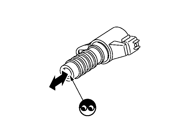
CAUTION:
Never apply 12 V continuously for 5 seconds or more. Doing so may result in damage to the coil in exhaust valve timing control solenoid valve.
 NOTE:
NOTE:
Always replace O-ring when exhaust valve timing control solenoid valve is removed.
Is the inspection result normal?
YES>>INSPECTION END
NO>>Replace malfunctioning exhaust valve timing control solenoid valve. Refer to Exploded View.
 P0075 Ivt Control Solenoid Valve
DTC Description
DTC DETECTION LOGIC
ECM detects an abnormal voltage in the intake valve timing control solenoid valve control circuit.
ECM detects an abnormal voltage in the intake valve timing intermediate lock control solenoid valve control circuit...
 P00fe Evap Control System
DTC Description
This diagnosis detects clogs in the EVAP line between fuel tank and EVAP canister purge volume control solenoid valve.ECM controls EVAP control system as below...
Other information:
Nissan Murano (Z52) 2015-2024 Owners Manual: Liftgate position setting (if so equipped)
The liftgate can be set to open to a specific height (garage mode) by performing the following: Open the liftgate using the liftgate instrument panel switch, liftgate opener switch or the Intelligent Key button. Pull the liftgate down and move to the desired height position (the liftgate will have some resistance when being manually adjusted)...
Nissan Murano (Z52) 2015-2024 Service Manual: P0420 Three Way Catalyst Function
DTC Description DTC DETECTION LOGICThe ECM monitors the switching frequency ratio of air fuel ratio (A/F) sensor 1 and heated oxygen sensor 2.A three way catalyst (manifold) with high oxygen storage capacity will indicate a low switching frequency of heated oxygen sensor 2...
Categories
- Manuals Home
- Nissan Murano Owners Manual
- Nissan Murano Service Manual
- Tire rotation
- System malfunction
- Power Steering Fluid (PSF)
- New on site
- Most important about car
Vehicle security system

Your vehicle has two types of security systems:
Vehicle security system NISSAN Vehicle Immobilizer SystemThe vehicle security system provides visual and audible alarm signals if someone opens the doors, liftgate or the hood when the system is armed. It is not, however, a motion detection type system that activates when a vehicle is moved or when a vibration occurs.