Nissan Murano: Dtc/circuit Diagnosis / P0075 Ivt Control Solenoid Valve
DTC DETECTION LOGIC
-
ECM detects an abnormal voltage in the intake valve timing control solenoid valve control circuit.
-
ECM detects an abnormal voltage in the intake valve timing intermediate lock control solenoid valve control circuit.
| DTC |
CONSULT screen terms (Trouble diagnosis content) |
DTC detection condition | |
| P0075 |
INT/V TIM V/CIR-B1 (Intake valve control solenoid circuit bank 1) |
Diagnosis condition | Start engine and let it idle |
| Signal (terminal) |
|
||
| Threshold |
|
||
| Diagnosis delay time | — | ||
| P0081 |
INT/V TIM V/CIR-B1 (Intake valve control solenoid circuit bank 2) |
Diagnosis condition | Start engine and let it idle |
| Signal (terminal) |
|
||
| Threshold |
|
||
| Diagnosis delay time | — | ||
POSSIBLE CAUSE
P0075
-
Harness or connectors
-
Intake valve timing control solenoid valve circuit is open or shorted.
-
Intake valve timing intermediate lock control solenoid valve circuit is open or shorted.
-
-
Intake valve timing control solenoid valve
-
Intake valve timing intermediate lock control solenoid valve
P0081
-
Harness or connectors
-
Intake valve timing control solenoid valve circuit is open or shorted.
-
Intake valve timing intermediate lock control solenoid valve circuit is open or shorted.
-
-
Intake valve timing control solenoid valve
-
Intake valve timing intermediate lock control solenoid valve
FAIL-SAFE
Not applicable
PRECONDITIONING
If DTC Confirmation Procedure has been previously conducted, always perform the following before conducting the next test.
-
Turn ignition switch OFF and wait at least 10 seconds.
-
Turn ignition switch ON.
-
Turn ignition switch OFF and wait at least 10 seconds.
>>
GO TO 2.
PERFORM DTC CONFIRMATION PROCEDURE
-
Start engine and let it idle for 5 seconds.
-
Check 1st trip DTC.
Is 1st trip DTC detected?
YES>>Proceed to Diagnosis Procedure.
NO>>To check malfunction symptom before repair: Refer to Intermittent Incident.
NO>>Confirmation after repair: INSPECTION END
CHECK INTAKE VALVE TIMING CONTROL SOLENOID VALVE POWER SUPPLY
-
Turn ignition switch OFF.
-
Disconnect intake valve timing (IVT) control solenoid valve harness connector.
-
Turn ignition switch ON.
-
Check the voltage between intake valve timing control solenoid valve harness connector and ground with CONSULT or tester.
DTC IVT control solenoid valve Ground Voltage Bank Connector Terminal P0075 1 F67 1 Ground Battery voltage P0081 2 F66 1
Is the inspection result normal?
YES>>GO TO 2.
NO>>Repair open circuit, short to ground or short to power in harness or connectors.
CHECK IVT CONTROL SOLENOID VALVE POWER SUPPLY CIRCUIT
-
Turn ignition switch OFF.
-
Disconnect IPDM E/R harness connector.
-
Check the continuity between IVT control solenoid valve harness connector and IPDM E/R harness connector.
DTC IVT control solenoid valve IPDM E/R Continuity Bank Connector Terminal Connector Terminal P0075 1 F67 1 F19 59 Existed P0081 2 F66 1 -
Also check harness for short to ground.
Is the inspection result normal?
YES>>GO TO 3.
NO>>Repair or replace error-detected parts.
CHECK INTAKE VALVE TIMING CONTROL SOLENOID VALVE OUTPUT SIGNAL CIRCUIT FOR OPEN AND SHORT
-
Turn ignition switch OFF.
-
Disconnect ECM harness connector.
-
Check the continuity between intake valve timing control solenoid valve harness connector and ECM harness connector.
DTC IVT control solenoid valve ECM Continuity Bank Connector Terminal Connector Terminal P0075 1 F67 2 F79 117 Existed P0081 2 F66 2 119 -
Also check harness for short to ground and short to power.
Is the inspection result normal?
YES>>GO TO 4.
NO>>Repair open circuit, short to ground or short to power in harness or connectors.
CHECK IVT CONTROL SOLENOID VALVE
Check the IVT control solenoid valve. Refer to Component Inspection (IVT Control Solenoid Valve).
Is the inspection result normal?
YES>>GO TO 5.
NO>>Replace IVT control solenoid valve. Refer to Exploded View.
CHECK IVT INTERMEDIATE LOCK CONTROL SOLENOID VALVE POWER SUPPLY
-
Disconnect IVT intermediate lock control solenoid valve harness connector.
-
Turn ignition switch ON.
-
Check the voltage between IVT intermediate lock control solenoid valve harness connector and ground.
DTC IVT intermediate lock control solenoid valve Ground Voltage Bank Connector Terminal P0075 1 F74 1 Ground Battery voltage P0081 2 F75 1
Is the inspection result normal?
YES>>GO TO 7.
NO>>GO TO 6.
CHECK IVT INTERMEDIATE LOCK CONTROL SOLENOID VALVE POWER SUPPLY CIRCUIT
-
Turn ignition switch OFF.
-
Disconnect IPDM E/R harness connector.
-
Check the continuity between IVT intermediate lock control solenoid valve harness connector and IPDM E/R harness connector.
DTC IVT intermediate lock control solenoid valve IPDM E/R Continuity Bank Connector Terminal Connector Terminal P0075 1 F74 1 F19 59 Existed P0081 2 F75 1 -
Also check harness for short to ground.
Is the inspection result normal?
YES>>Perform the trouble diagnosis for power supply circuit.
NO>>Repair or replace error-detected parts.
CHECK IVT INTERMEDIATE LOCK CONTROL SOLENOID VALVE GROUND CIRCUIT
-
Turn ignition switch OFF.
-
Disconnect ECM harness connector.
-
Check the continuity between IVT intermediate lock control solenoid valve harness connector and ECM harness connector.
DTC IVT intermediate lock control solenoid valve ECM Continuity Bank Connector Terminal Connector Terminal P0075 1 F74 2 F79 118 Existed P0081 2 F75 2 120 -
Also check harness for short to ground and short to power.
Is the inspection result normal?
YES>>GO TO 8.
NO>>Repair or replace error-detected parts.
CHECK IVT INTERMEDIATE LOCK CONTROL SOLENOID VALVE
Check the IVT intermediate lock control solenoid valve. Refer to Component Inspection (IVT Intermediate Lock Control Solenoid Valve).
Is the inspection result normal?
YES>>INSPECTION END
NO>>Replace IVT intermediate lock control solenoid valve. Refer to Exploded View.
CHECK INTAKE VALVE TIMING CONTROL SOLENOID VALVE-I
-
Turn ignition switch OFF.
-
Disconnect intake valve timing control solenoid valve harness connector.
-
Check resistance between intake valve timing control solenoid valve terminals as follows.
Intake valve timing control solenoid valve Condition
Resistance + − Terminal 1 2 Temperature 20°C (68°F) 7.0 – 7.8 Ω 1 Ground ∞
(Continuity should not exist)2
Is the inspection result normal?
YES>>GO TO 2.
NO>>Replace intake valve timing control solenoid valve. Refer to Exploded View.
CHECK INTAKE VALVE TIMING CONTROL SOLENOID VALVE-II
-
Remove intake valve timing control solenoid valve. Refer to Exploded View.
-
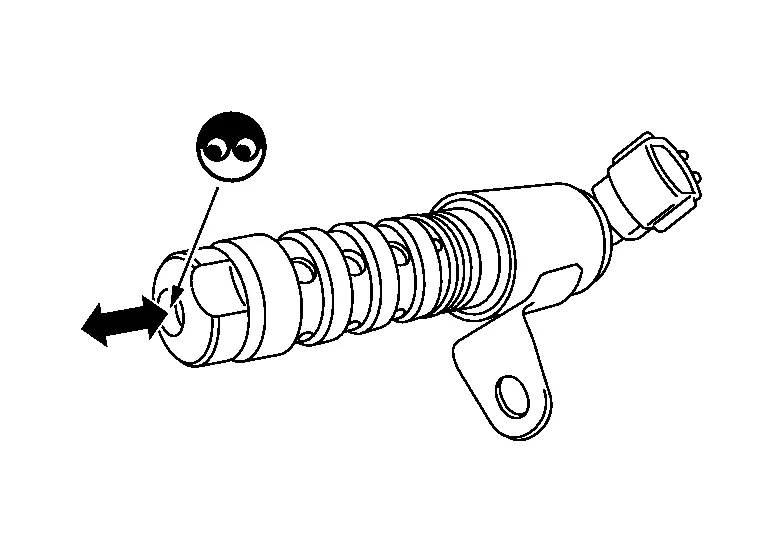
Provide 12 V DC between intake valve timing control solenoid valve terminals 1 and 2, and then interrupt it. Make sure that the plunger moves as shown in the figure.
CAUTION:
Do not apply 12 V DC continuously for 5 seconds or more. Doing so may result in damage to the coil in intake valve timing control solenoid valve.
 NOTE:
NOTE:
Always replace O-ring when intake valve timing control solenoid valve is removed.
Is the inspection result normal?
YES>>INSPECTION END
NO>>Replace intake valve timing control solenoid valve. Refer to Exploded View.
CHECK INTAKE VALVE TIMING INTERMEDIATE LOCK CONTROL SOLENOID VALVE-I
-
Turn ignition switch OFF.
-
Disconnect intake valve timing intermediate lock control solenoid valve harness connector.
-
Check resistance between intake valve timing intermediate lock control solenoid valve terminals as follows.
Intake valve timing intermediate lock control solenoid valve Condition
Resistance + − Terminal 1 2 Temperature 20°C (68°F) 7.0 – 7.8 Ω 1 Ground ∞
(Continuity should not exist)2
Is the inspection result normal?
YES>>GO TO 2.
NO>>Replace intake valve timing intermediate lock control solenoid valve. Refer to Exploded View.
CHECK INTAKE VALVE TIMING INTERMEDIATE LOCK CONTROL SOLENOID VALVE-II
-
Remove intake valve timing intermediate lock control solenoid valve. Refer to Exploded View.
-
Provide 12 V DC between intake valve timing intermediate lock control solenoid valve terminals 1 and 2, and then interrupt it. Make sure that the plunger moves as shown in the figure.
CAUTION:
Do not apply 12 V DC continuously for 5 seconds or more. Doing so may result in damage to the coil in intake valve timing intermediate lock control solenoid valve.
NOTE:
Always replace O-ring when intake valve timing intermediate lock control solenoid valve is removed.
Is the inspection result normal?
YES>>INSPECTION END
NO>>Replace intake valve timing intermediate lock control solenoid valve. Refer to Exploded View.
 P0053 A/f Sensor 1 Heater
DTC Description
DTC DETECTION LOGIC DTC
CONSULT screen terms
(Trouble diagnosis content)
DTC detection condition
P0053
HO2S1 HTR B1
(HO2S heater resistance bank 1 sensor 1)
Diagnosis condition
—
Signal (terminal)
A/F sensor 1 heater (bank 1) signal
Threshold
During engine running, weighted average of A/F sensor internal resistance is out of the normal range
Diagnosis delay time
—
POSSIBLE CAUSE
Harness and connectors [A/F sensor 1 (bank 1) heater circuit is open or shorted...
 P0078 Evt Control Solenoid Valve
DTC Description
DTC DETECTION LOGICAn improper voltage is sent to the ECM through exhaust valve timing control solenoid valve. DTC
CONSULT screen terms
(Trouble diagnosis content)
DTC detection condition
P0078
EX V/T ACT/CIRC-B1
[Exhaust valve timing control solenoid valve (bank 1) circuit]
Diagnosis condition
Start engine and let it idle
Signal (terminal)
Voltage signal transmitted from exhaust valve timing control solenoid valve to ECM
Threshold
An improper voltage is sent to the ECM through exhaust valve timing control solenoid valve
Diagnosis delay time
—
P0084
EX V/T ACT/CIRC-B2
[Exhaust valve timing control solenoid valve (bank 2) circuit]
Diagnosis condition
Start engine and let it idle
Signal (terminal)
Voltage signal transmitted from exhaust valve timing control solenoid valve to ECM
Threshold
An improper voltage is sent to the ECM through exhaust valve timing control solenoid valve
Diagnosis delay time
—
POSSIBLE CAUSEP0078
Harness or connectors (Exhaust valve timing control solenoid valve circuit is open or shorted...
Other information:
Nissan Murano (Z52) 2015-2024 Service Manual: Defogger :: Ecu Diagnosis Information. Bcm, A/c Auto Amp.
..
Nissan Murano (Z52) 2015-2024 Owners Manual: Remove and Install
Remove Use the following procedure to remove the head restraint/headrest: Pull the head restraint/headrest up to the highest position. Push and hold the lock knob. Remove the head restraint/headrest from the seat. Store the head restraint/headrest properly in a secure place so it is not loose in the vehicle...
Categories
- Manuals Home
- Nissan Murano Owners Manual
- Nissan Murano Service Manual
- Tire rotation
- GAS STATION INFORMATION
- Shift lock release
- New on site
- Most important about car
Driver and passenger supplemental knee air bag

Driver’s side
The knee air bag is located in the knee bolster, on the driver’s and passenger’s side. All of the information, cautions and warnings in this manual apply and must be followed. The knee air bag is designed to inflate in higher severity frontal collisions, although it may inflate if the forces in another type of collision are similar to those of a higher severity frontal impact. It may not inflate in certain collisions.

Passenger’s side