Nissan Murano: System Description / Operation. Automatic Speed Control Device (ascd)
SWITCHES AND INDICATORS
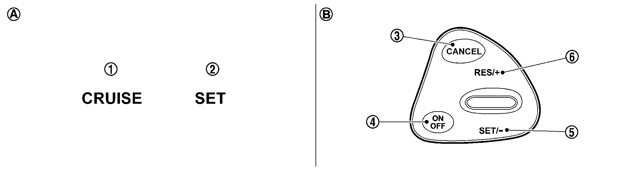
| 1. | CRUISE indicator | 2. | SET indicator | 3. | CANCEL switch |
| 4. | ON/OFF (MAIN) switch | 5. | SET- | 6. | RES+ |
| A. | On the combination meter (Information display) | B. | On the steering wheel |
SET SPEED RANGE
ASCD system can be set the following vehicle speed.
| Minimum speed (Approx.) | Maximum speed (Approx.) |
|---|---|
| 40 km/h (25 MPH) | 144 km/h (89 MPH) |
SWITCH OPERATION
| Item | Function |
|---|---|
| CANCEL switch | Cancels the cruise control driving. |
| RES+ |
|
| SET- |
|
| ON/OFF (MAIN) switch | Master switch to activate the ASCD system. |
CANCEL OPERATION
When any of following conditions exist, cruise operation will be canceled.
-
CANCEL switch is pressed
-
ON/OFF (MAIN) switch pressed (Set speed is cleared)
-
More than 2 switches at ASCD steering switch are pressed at the same time (Set speed will be cleared)
-
Brake pedal is depressed
-
Selector lever position is changed to N, P or R
-
Nissan Murano Vehicle speed decreased to 13 km/h (8 MPH) lower than the set speed
-
TCS system is operated
When the ECM detects any of the following conditions, the ECM will cancel the cruise operation and inform the driver by blinking indicator.
-
Engine coolant temperature is slightly higher than the normal operating temperature, CRUISE indicator may blink slowly.
When the engine coolant temperature decreases to the normal operating temperature, CRUISE indicator will stop blinking and the cruise operation will be able to work by pressing SET- switch or RES+ switch.
-
Malfunction for some self-diagnoses regarding ASCD control: SET indicator will blink quickly.
If MAIN switch is turned to OFF during ASCD is activated, all of ASCD operations will be canceled and Nissan Murano vehicle speed memory will be erased.
 Fuel Pump Control Module (fpcm)
System Description
SYSTEM DIAGRAM*1: ECM determines the start signal status by the signals of engine speed and battery voltage.*2: This sensor is not used to control the engine system under normal conditions...
 On Board Diagnostic (obd) System
Diagnosis Description
This system is an on board diagnostic system that records exhaust emission-related diagnostic information and detects a sensors/actuator-related malfunction...
Other information:
Nissan Murano (Z52) 2015-2024 Service Manual: Additional Service When Replacing Sonar Control Unit
Description BEFORE REPLACEMENTWhen replacing sonar control unit, save or print current vehicle specification with CONSULT configuration before replacement.NOTE: If “Before Replace ECU” cannot be used, use the “After Replace ECU” or “Manual Configuration” after replacing sonar control unit...
Nissan Murano (Z52) 2015-2024 Service Manual: Heating and Cooling Unit Assembly
Exploded View 1. Heating and cooling unit assembly 2. Steering member 3. Steering member brace (LH) 4. Steering member brace (RH) A. Steering member caps Pawl Front 1. Heating and cooling unit assembly 2...
Categories
- Manuals Home
- Nissan Murano Owners Manual
- Nissan Murano Service Manual
- Warning lights
- Settings
- Passenger compartment
- New on site
- Most important about car
Autolight system
The autolight system allows the headlights to turn on and off automatically. The autolight system can:
Turn on the headlights, front parking, tail, license plate and instrument panel lights automatically when it is dark. Turn off all the lights (except daylight running lights) when it is light. Keep all the lights on for a period of time after you place the ignition switch in the OFF position and all doors are closed.