Nissan Murano: Srs Air Bag :: Removal and Installation / Occupant Classification System
OCCUPANT CLASSIFICATION SYSTEM CONTROL UNIT
WARNING:
-
Before servicing SRS, place the ignition switch in the OFF position, disconnect both battery terminals then wait at least three minutes.
-
Do not use air tools or electric tools for servicing.
REMOVAL
Slide front passenger seat to full forward position.
Remove occupant classification system control unit bolts.
Disconnect harness connector from occupant classification system control unit.
Remove occupant classification system control unit.
CAUTION:
-
lace occupant classification control unit if it has been dropped or sustained an impact.
-
Do not strike occupant classification control unit.
INSTALLATION
Installation is in the reverse order of removal.
CAUTION:
-
Do not damage harness connector during installation.
-
After installation is complete, check that no system malfunction is detected causing air bag warning lamp to illuminate.
-
If a malfunction is indicated by the air bag warning lamp after repair or replacement of the malfunctioning parts, perform the SRS final check. Refer to SRS Final Check.
OCCUPANT CLASSIFICATION SYSTEM SENSORS
WARNING:
-
When working near the Airbag Diagnosis Sensor Unit or other Airbag System sensors with the Ignition ON or engine running, DO NOT use air or electric power tools or strike near the sensor(s) with a hammer. Heavy vibration could activate the sensor(s) and deploy the air bag(s), possibly causing serious injury.
-
Before servicing SRS, place the ignition switch in the OFF position, disconnect both battery terminals then wait at least 3 minutes.
CAUTION:
-
When working with the metal seat frame, use caution to avoid injury from sharp edges.
-
When removing or installing the seat trim, handle it carefully to keep dirt out and to avoid damage.
-
When removing or installing the seat, use shop cloths to protect components from damage.
-
When disconnecting or connecting the harness and harness connectors, handle them carefully to avoid damage.
REMOVAL
Remove the seat cushion outer finisher (RH) from the front passenger seat using the following procedure.For models with power front passenger seat, use the following steps.
-
Release the seat cushion outer finisher (RH) pawls.
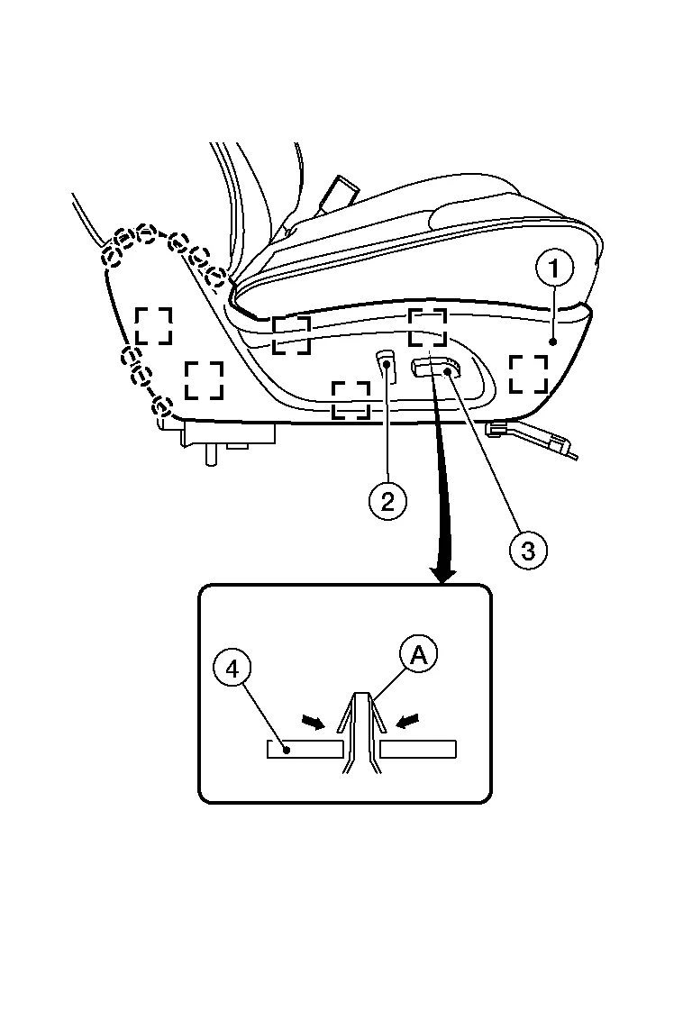

: Pawl -
Release the metal clips (A) from the seat frame (2) as shown, and pull the seat cushion outer finisher (RH) (1) away from the seat assembly.

: Metal clip -
Disconnect the harness connector from the power seat switch.
-
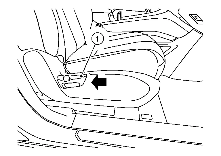
Release the pawl and remove the recline lever finisher (1) from the recline lever as shown.
: Pawl -
Release the seat cushion outer finisher (RH) pawls.
: Pawl -
Release the metal clips (A) from the seat frame (2) as shown, and pull the seat cushion outer finisher (RH) (1) away from the seat assembly.
: Metal clip
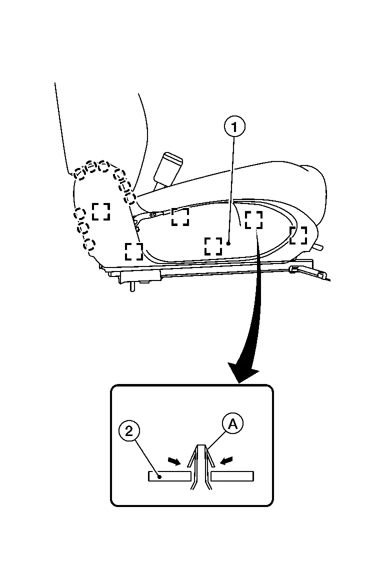
From under the rear of the front passenger seat, release the seatback J-clips and position aside.
Remove the front passenger seat cushion assembly from the seat frame assembly using the following procedure.Release the rear J-hooks.
-
For models with climate controlled passenger seat, release the rear J-hooks (A) from the seat frame assembly

: Front -
For models without climate controlled passenger seat, release the rear hinge cover J-hooks (A) from the seat frame assembly (1).

: Front
| : Front |
CAUTION:
Do not damage center console finishers or seat cushion trim.
 NOTE:
NOTE:
Push the J-hook (B) down and away from the seat frame assembly using suitable tool (A) as shown.
Release the seat cushion trim J-hook (A) from the RH (outboard) side of the seat frame assembly.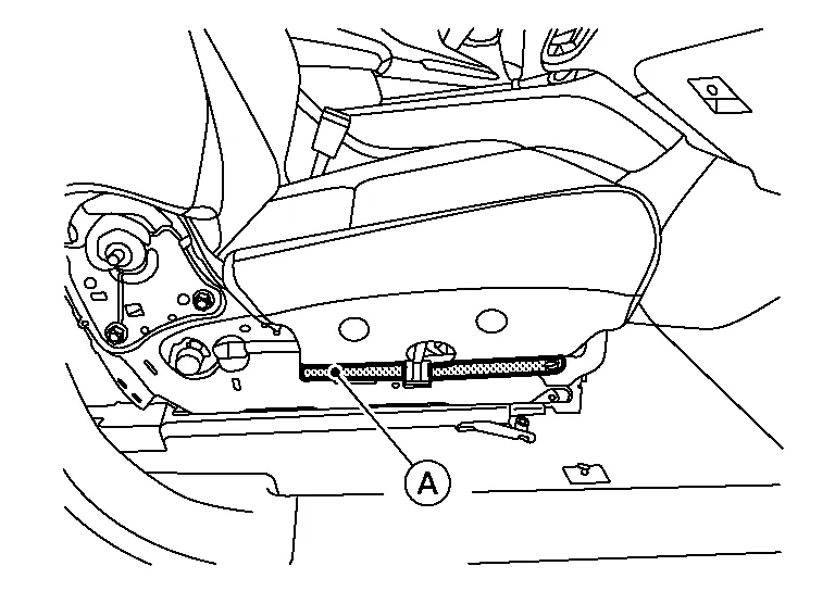
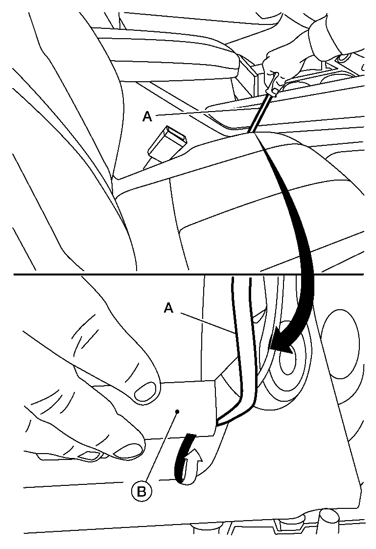
Release the harness clip and disconnect the harness connectors from the front passenger seat.
-
For models with power front passenger seat, release the harness clip (A) from the seat frame assembly, then disconnect the harness connectors (B).
-
For models with manual front passenger seat, release the harness clip (A) from the seat frame assembly, then disconnect the harness connectors (B).
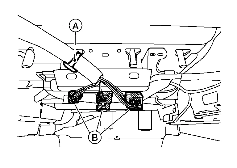
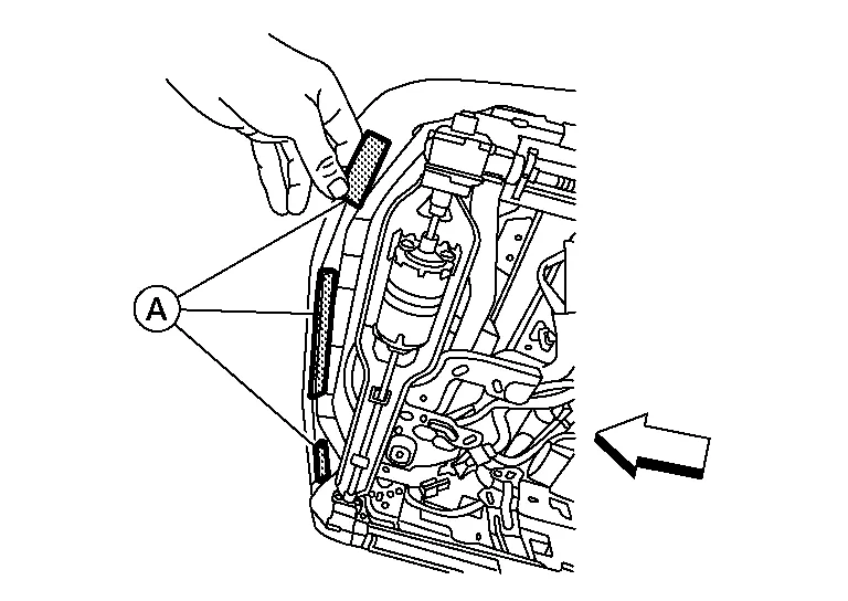
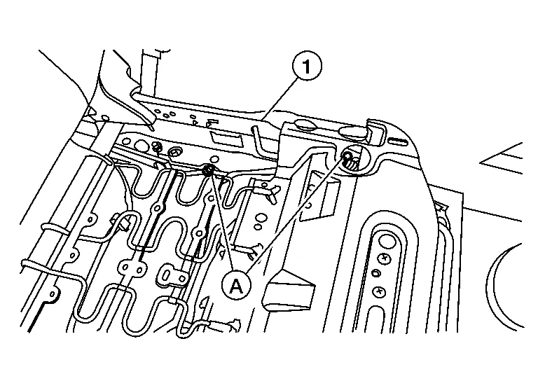
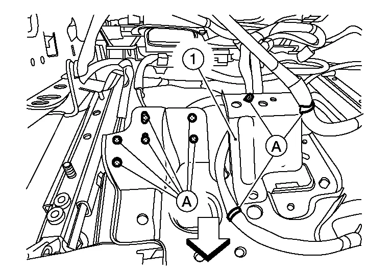
Release the occupant classification system sensors harness clips (A) from the seat frame assembly (1).
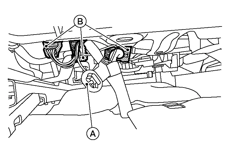
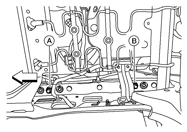
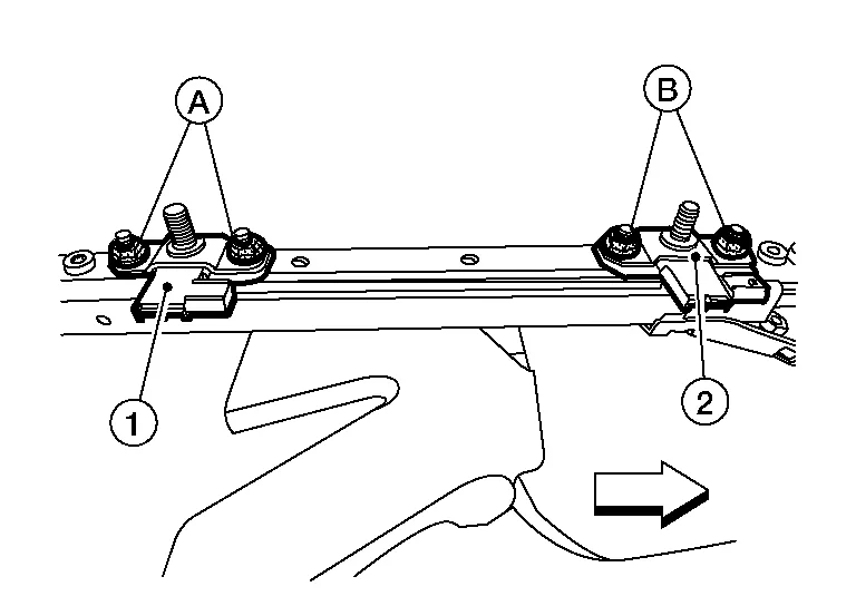
Remove the seat frame assembly nuts from the seat tracks using the following procedure.Remove washer and nut (A) from the front LH (inboard) side of the seat frame assembly, and nut (B) from the rear LH (inboard) side of the seat frame assembly.
CAUTION:
-
Do not move the seat track while the nuts (A,B) are removed.
-
Do not reuse washer and nut (A) or nut (B).
| : Front |
CAUTION:
-
Do not move the seat track while nuts (A) are removed.
-
Do not reuse nuts (A).
![]() : Front
: Front
Tilt the front passenger seat forward and disconnect the harness connector from the rear occupant classification system sensor.
Disconnect the harness connector from the front occupant classification system sensor.
For models with power front passenger seat, perform the following procedure.Tilt the front passenger seat rearward and release the harness clips (A) from the seat frame assembly (1).
| : Front |
Remove the front passenger seat frame assembly from the seat tracks and position to the rear.
Remove the occupant classification system sensors using the following procedure.
| : Front |
INSTALLATION
WARNING:
-
After installation is complete, perform additional services (Zero point reset) when installing occupant classification system sensors. Refer to Special Repair Requirement.
-
Zero point reset must be performed every time the front passenger seat is removed.
-
Zero point reset is done after the front passenger seat is installed in Nissan Murano vehicle and all nuts and bolts are tightened to specification.
CAUTION:
-
After installation is complete, check that no system malfunction is detected causing the air bag warning lamp to illuminate.
-
If a malfunction is indicated by the air bag warning lamp after repair or replacement of the malfunctioning parts, perform the SRS final check. Refer to SRS Final Check.
Install the occupant classification system sensors using the following procedure.Install the rear occupant classification system sensor (1) and nuts (A) and tighten to specification.
CAUTION:
Do not reuse nuts (A).
| : Front |
| Occupant classification system sensor nuts (A) | : 22 N·m (2.2 kg-m, 16 ft-lb) |
CAUTION:
Do not reuse nuts (B).
| Occupant classification system sensor nuts (B) | : 22 N·m (2.2 kg-m, 16 ft-lb) |
Install the seat frame assembly onto the four studs.
CAUTION:
Make sure the seat frame assembly is installed correctly on all four studs.
For models with power front passenger seat, perform the following procedure.Tilt the front passenger seat rearward and attach the harness clips (A) to the seat frame assembly (1).
| : Front |
Connect the front occupant classification system sensor harness connector.
Tilt the front passenger seat forward and connect the rear occupant classification system sensor harness connector.
Install the front passenger seat frame assembly using the following procedure.Install washer and nut (A) to the front LH (inboard) side of the seat frame assembly and hand tighten.
CAUTION:
Do not reuse washer and nut (A).
| : Front |
CAUTION:
Do not reuse nut (B).
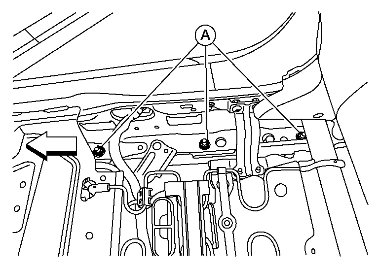
Install nuts (A) to the RH (outboard) side of the seat frame assembly and tighten to specification.
CAUTION:
Do not reuse nuts (A).
| : Front |
| Seat frame assembly nuts (A) | : 45 N·m (4.6 kg-m, 33 ft-lb) |
CAUTION:
Do not reuse washer and nut (A).
| : Front |
| Seat frame assembly nut (A) | : 45 N·m (4.6 kg-m, 33 ft-lb) |
CAUTION:
Do not reuse nut (B).
| Seat frame assembly nut (B) | : 45 N·m (4.6 kg-m, 33 ft-lb) |
Attach the occupant classification system sensors harness clips (A) to the seat frame assembly (1).
Attach the harness clip and connect the harness connectors to the front passenger seat.
-
For models with power front passenger seat, attach the harness clip (A) to the seat frame assembly, then connect the harness connectors (B).
-
For models with manual front passenger seat, attach the harness clip (A) to the seat frame assembly, then connect the harness connectors (B).
Install the seat cushion assembly using the following procedure.Attach the rear J-hooks.
-
For models with climate controlled passenger seat, release the rear J-hooks (A) from the seat frame assembly
: Front -
For models without climate controlled passenger seat, attach the rear hinge cover J-hooks (A) to the seat frame assembly (1).
: Front
| : Front |

CAUTION:
Do not damage center console finishers or seat cushion trim.
NOTE:
Push the J-hook (B) down and towards the seat frame assembly using suitable tool (A) as shown.
Attach the seat cushion trim J-hook (A) to the RH (outboard) side of the seat frame assembly.
Attach the seatback J-clips under the rear of the front passenger seat.
Install the seat cushion outer finisher (RH) to the front passenger seat using the following procedure.For models with power front passenger seat, use the following steps.
-
Connect the power seat switch harness connector.
-
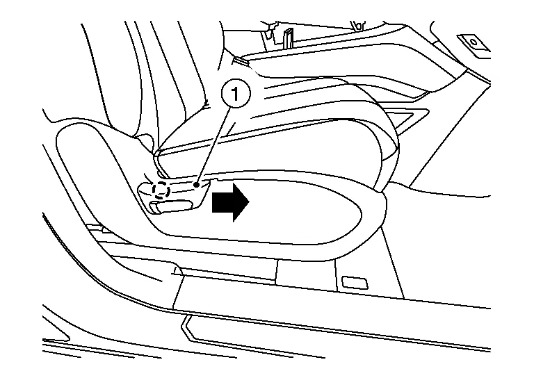
Install the seat cushion outer finisher (RH) (1) to the front passenger seat.
NOTE:
Make sure the metal clips (A) are secured into the seat frame (2).
: Pawl : Metal clip
-
Install the seat cushion outer finisher (RH) (1) to the front passenger seat.
NOTE:
Make sure the metal clips (A) are secured into the seat frame (2).
: Pawl : Metal clip -
Install the recline lever finisher (1) to the recline lever as shown.
 NOTE:
NOTE:
Push recline lever finisher onto recline lever until the pawl locks into place.
: Pawl
For models with manual passenger seat, operate seat slide and make sure both tracks lock in place at each adjustment point.
 Front Seat Belt Buckle Switch
Removal and Installation
The front seat belt buckle switch is part of the front seat belt buckle. For removal and installation of the front seat belt buckle, refer to Removal and Installation...
 Front Passenger Air Bag Off Indicator
Removal and Installation
REMOVALRemove A/C switch assembly. Refer to Removal and Installation.
Remove screws and front passenger air bag OFF indicator...
Other information:
Nissan Murano (Z52) 2015-2024 Service Manual: Evaporator
Removal and Installation Heating and Cooling Unit Components 1. Heating and cooling unit assembly 2. Evaporator 3. Heater case side cover 4. Air mix door motor (RH) 5. Blower unit case 6. Intake door motor 7. Blower motor 8...
Nissan Murano (Z52) 2015-2024 Service Manual: Door Sash Molding
Exploded View 1. Front door sash molding 2. Rear door rear sash molding 3. Front door panel 4. Rear door panel Removal and Installation FRONT DOORRemovalRemove door mirror. Refer to Removal and Installation. Remove front door sash molding clip (A) using a suitable tool (B)...
Categories
- Manuals Home
- Nissan Murano Owners Manual
- Nissan Murano Service Manual
- Jacking up vehicle and removing the damaged tire
- Indicator lights
- Turning the AEB system on/off
- New on site
- Most important about car
Front manual seat adjustment (if so equipped)
Your vehicle seats can be adjusted manually. For additional information about adjusting the seats, refer to the steps outlined in this section.
Forward and backward
