Nissan Murano: Power Window Control System :: Ecu Diagnosis Information / Main Power Window and Door Lock/unlock Switch
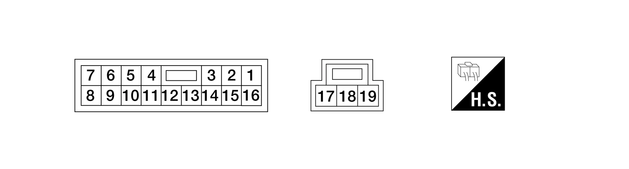
TERMINAL LAYOUT
PHYSICAL VALUES
|
Terminal No. (wire color) | Description | Condition |
Voltage (Approx.) | ||
|---|---|---|---|---|---|
| + | - | Signal name | Input/Output | ||
|
1 (B) |
Ground | Ground | Output | — | 0 |
|
4 (R) |
12 (Y) |
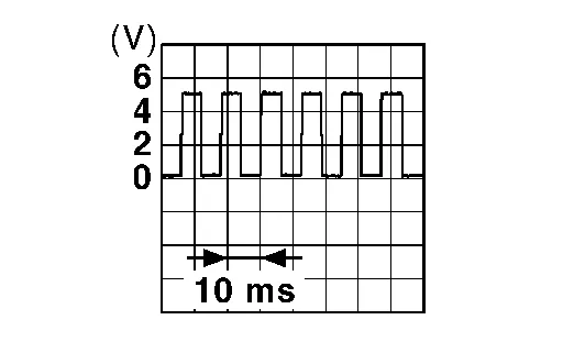
Encoder pulse signal 2 | Input | When power window motor operates |
|
|
5 (Y) |
12 (Y) |
Encoder pulse signal 1 | Input | When power window motor operates |
|
|
6 (L) |
Ground | Rear power window motor RH DOWN signal. | Output | When rear power window switch RH is operated DOWN | Battery voltage |
|
7 (V) |
Ground | Rear power window motor RH UP signal. | Output | When rear power window switch RH is operated UP | Battery voltage |
|
8 (LG) |
Ground | Rear power window motor LH DOWN signal. | Output | When rear power window switch LH is operated DOWN | Battery voltage |
|
9 (SB) |
Ground | Rear power window motor LH UP signal. | Output | When rear power window switch LH is operated UP | Battery voltage |
|
10 (BR) |
Ground | Ignition switch power supply | Input | Ignition switch ON | Battery voltage |
| Other than above | 0 | ||||
|
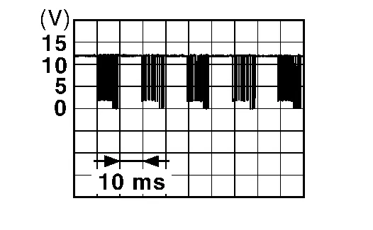
11 (Y/L) |
Ground | Power window serial link | Input/Output | IGN SW ON or power window operating. |
|
|
12 (Y) |
Ground | Encoder ground | — | — | 0 |
|
14 (P) |
Ground | Encoder power supply | Output | When ignition is ON or power window timer operates. | Battery voltage |
|
17 (G) |
19 (Y) |
Main power window and door lock/unlock switch UP signal | Output | When main power window and door lock/unlock switch is operated UP | Battery voltage |
|
18 (Y) |
Ground | Battery power supply | Input | — | Battery voltage |
|
19 (Y) |
17 (G) |
Main power window and door lock/unlock switch DOWN signal | Output | When main power window and door lock/unlock switch is operated DOWN | Battery voltage |
FAIL-SAFE CONTROL
Switches to fail-safe control when malfunction is detected in encoder signal that detects up/down speed and direction of door glass. Switches to fail-safe control when an error beyond the regulation value is detected between the fully closed position and the actual position of the glass.
| Malfunction | Malfunction condition |
|---|---|
| Pulse sensor malfunction | When only one side of pulse signal is being detected for more than the specified value. |
| Both pulse sensors malfunction | When both pulse signals have not been detected for more than the specified value during glass open/close operation. |
| Pulse direction malfunction | When the pulse signal that is detected during glass open/close operation detects the opposite condition of power window motor operating direction. |
| Glass recognition position malfunction 1 | When it detects the error between glass fully closed position in power window switch memory and actual fully closed position during glass open/close operation is more than the specified value. |
| Glass recognition position malfunction 2 | When it detects pulse count more that the value of glass full stroke during glass open/close operation. |
| Malfunction of not yet updated closed position of glass | When glass open/close operation is continuously performed without fully closing more that the specified value (approximately 10 strokes). |
It changes to condition before initialization and the following functions do not operate when switched to fail-safe control:
-
Auto-up operation
-
Anti-pinch function
-
Retained power function
Perform initial operation to recover when switched to fail-safe mode. However, it switches back to fail-safe control when malfunction is found in power window switch or in motor.

 Power Window and Door Lock/unlock Switch Rh
Reference Value
TERMINAL LAYOUTPHYSICAL VALUES
Terminal No.
(wire color) Description Condition
Voltage
(Approx.)
+ - Signal name Input/Output
3
(Y/L)
Ground
Power window serial link
Input/Output
IGN SW ON or power window operating
4
(B)
Ground
Encoder ground
—
—
—
5
(L/W)
Ground
Encoder power supply
Output
When ignition switch ON or power window timer operates...
Other information:
Nissan Murano (Z52) 2015-2024 Owners Manual: Vehicle-to-vehicle distance control mode limitations
WARNING Listed below are the system limitations for the ICC system. Failure to operate the vehicle in accordance with these system limitations could result in serious injury or death. The ICC system is primarily intended for use on straight, dry, open roads with light traffic...
Nissan Murano (Z52) 2015-2024 Service Manual: C1734 Control Unit
DTC Description NOTE: The Signal Tech II Tool [– (J-50190)] can be used to perform the following functions: Refer to the Signal Tech II User Guide for additional information. Activate and display TPMS sensor IDs Display tire pressure reported by the TPMS sensor Read TPMS DTCs Register TPMS sensor IDs DTC DETECTION LOGIC DTC No...
Categories
- Manuals Home
- Nissan Murano Owners Manual
- Nissan Murano Service Manual
- GAS STATION INFORMATION
- Indicator lights
- Settings
- New on site
- Most important about car
Vehicle security system

Your vehicle has two types of security systems:
Vehicle security system NISSAN Vehicle Immobilizer SystemThe vehicle security system provides visual and audible alarm signals if someone opens the doors, liftgate or the hood when the system is armed. It is not, however, a motion detection type system that activates when a vehicle is moved or when a vibration occurs.