
Nissan Murano: Liftgate / Liftgate release
Nissan Murano (Z52) 2015-2024 Owners Manual / Pre-driving checks and adjustments / Liftgate / Liftgate release
WARNING
- Always be sure the liftgate has been closed securely to prevent it from opening while driving.
- Do not drive with the liftgate open. This could allow dangerous exhaust gases to be drawninto the vehicle. For additional information, refer to “Exhaust gas (carbon monoxide)” in the “Starting and driving” section of this manual.
- To avoid personal injury, do not attempt to activate the power liftgate if one or both of the liftgate struts are removed.
- If the power liftgate does not stay open or if the liftgate unexpectedly closes at any time while a continuous warning chime sounds, do not operate the liftgate. There may be a pressure loss in one or both of the liftgate struts. It is recommended that you have the liftgate inspected. It is recommended that you visit a NISSAN dealer for this service.
- Do not activate the power liftgate if one or both of the liftgate struts are removed. Damage to the liftgate or power liftgate mechanisms may occur.
Liftgate release (manual and power)
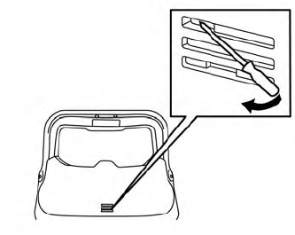
The liftgate release mechanism allows the liftgate to be opened in the event of a discharged battery.
To release the liftgate fromthe inside of the vehicle, perform the following operations:
- Position the rear bench seat forward. For additional information, refer to “Rear bench seat adjustment” in the “Safety—Seats, seat belts and supplemental restraint system” section of this manual.
- Insert a suitable tool into the top access opening at about a 45 degree angle and rotate to the left until the lock releases.
- Push the liftgate up to open.
NOTE:
If you had to open the liftgate using this procedure, have your vehicle checked as soon as possible. It is recommendedthat you visit a NISSAN dealer for this service.
 Motion-Activated Liftgate (if so equipped)
The liftgate can be operated using a quick
kicking motion under the center of the rear
bumper.
To operate, the Intelligent Key must be
within 31.5 in (80 cm) of the liftgate...
 Liftgate position setting (if so equipped)
The liftgate can be set to open to a specific
height (garage mode) by performing the
following:
Open the liftgate using the liftgate instrument
panel switch, liftgate opener
switch or the Intelligent Key button...
Other information:
Nissan Murano (Z52) 2015-2024 Owners Manual: Traffic Sign Recognition (TSR) (if so equipped)
The TSR system provides the driver with information about the most recently detected speed limit. The system captures the road sign information with the multisensing front camera unit located on the windshield in front of the inside rearview mirror and displays the detected signs in the vehicle information display...
Nissan Murano (Z52) 2015-2024 Service Manual: Seat Belt :: Preparation. Preparation
..
Categories
- Manuals Home
- Nissan Murano Owners Manual
- Nissan Murano Service Manual
- High Beam Assist (if so equipped)
- Fuel recommendation
- Rear bench seat adjustment
- New on site
- Most important about car
Front manual seat adjustment (if so equipped)
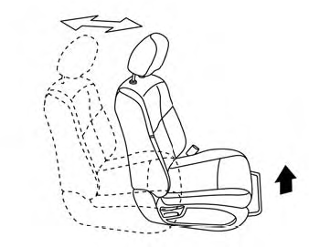
Your vehicle seats can be adjusted manually. For additional information about adjusting the seats, refer to the steps outlined in this section.
Forward and backward

Copyright © 2026 www.nimurano.com