Nissan Murano: Power Supply, Ground & Circuit Elements :: Basic Inspection / Fuse Inspection
-
If fuse is blown, be sure to eliminate cause of malfunction before installing new fuse.
-
Use fuse of specified rating. Never use fuse of more than specified rating.
-
Do not partially install fuse; always insert it into fuse holder properly.
-
Remove fuse for “ELECTRICAL PARTS (BAT)” if Nissan Murano vehicle is not used for a long period of time.
EXTENDED STORAGE SWITCH (IF EQUIPPED)
 NOTE:
NOTE:
-
When extended storage switch is pulled out, a message may be shown in the meter or display. To turn message/display off, push extended storage switch in.
-
The following information is related to extended storage switch (shipping mode). For information related to BCM transit mode, refer to System Description.
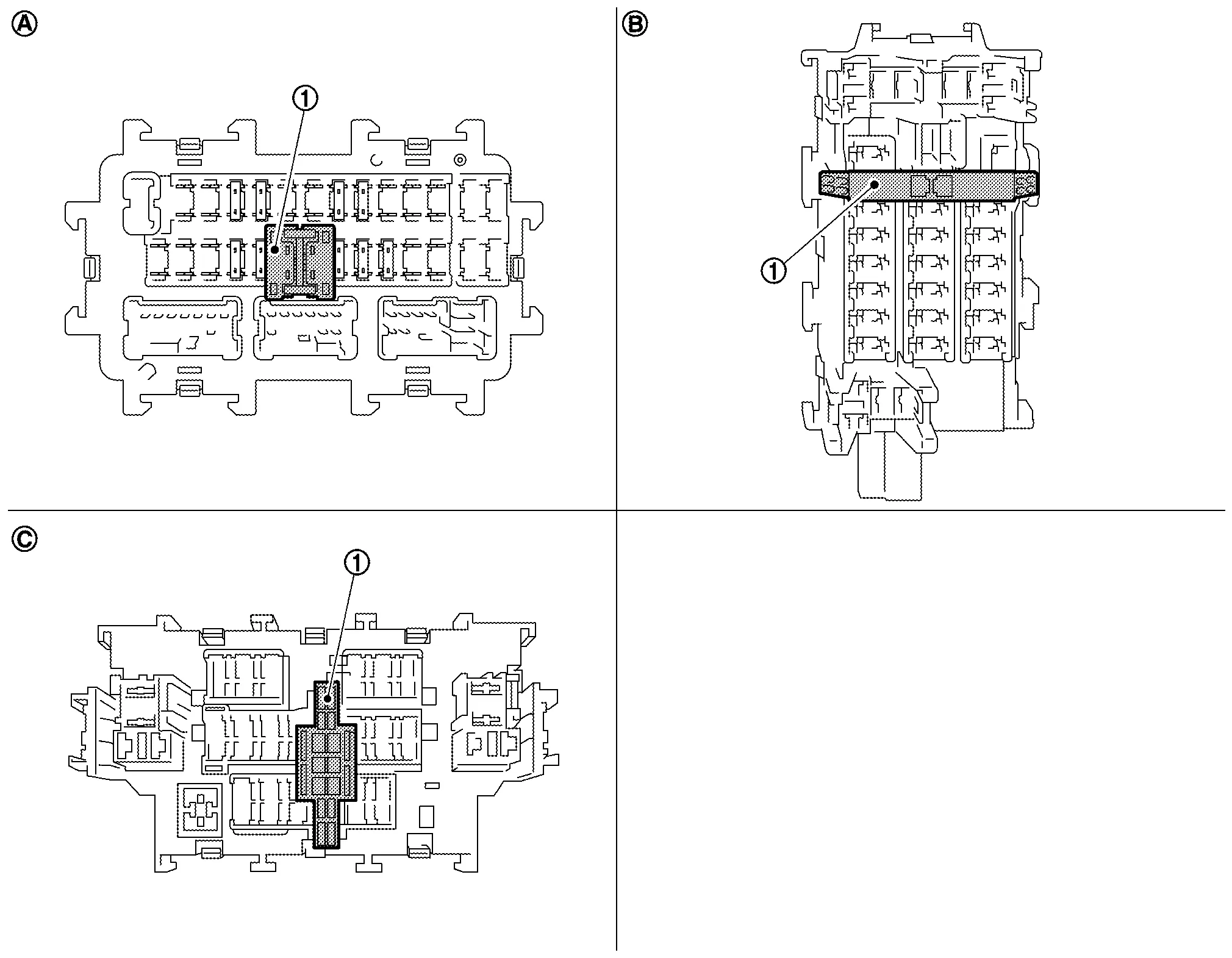
The following switch may be mounted on the fuse block (Junction Box) for transportation and storage.
 |
Extended storage switch | ||||
 |
Type A |  |
Type B |  |
Type C |
Remove the extended storage switch if it interferes when checking fuses.
How/When to turn Extended Storage Switch ON/OFF
CAUTION:
-
Ignition switch OFF when operating the extended storage switch.
-
Under normal conditions, keep the extended storage switch in ON state. Never operate the extended storage switch except when necessary.
-
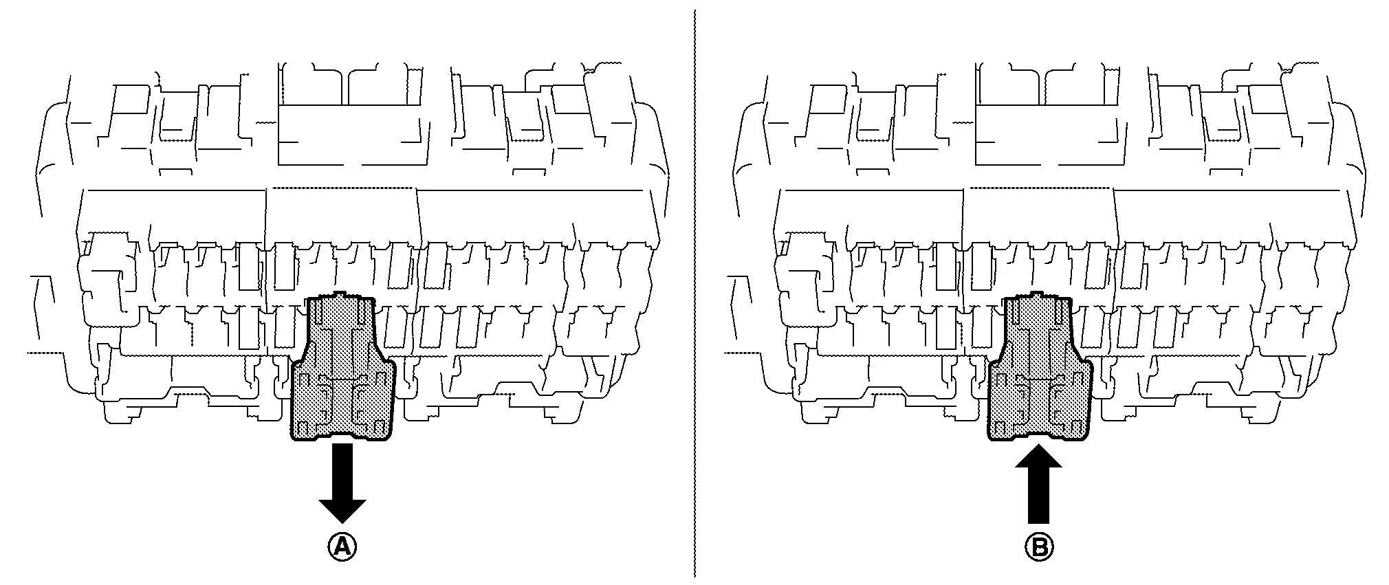
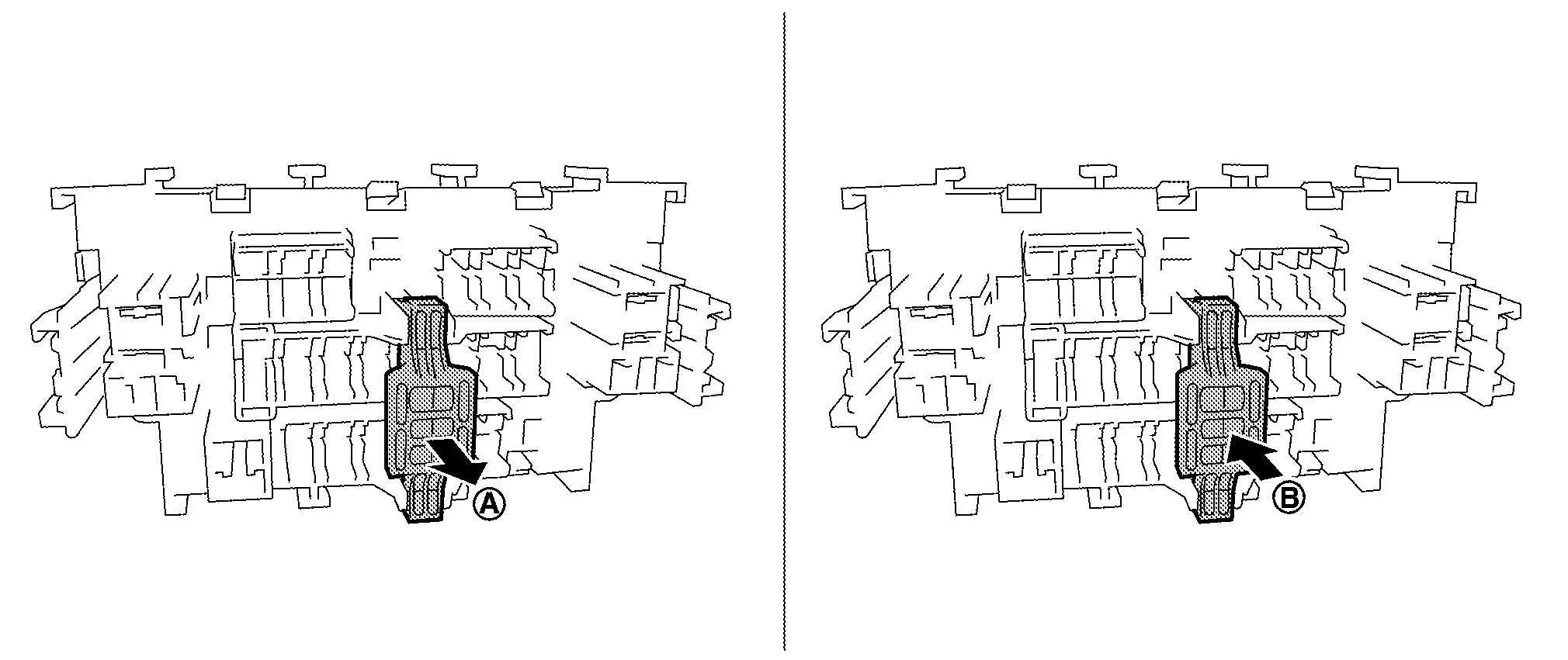
Type A
-
To place the extended storage switch in the OFF position, pull out in
direction as shown in the figure. -
To place the extended storage switch in the ON position, press in
direction as shown in the figure.
-
-
Type B
-
To place the extended storage switch in the OFF position, pinch tabs
of the switch and pull out in direction as shown in the figure. -
To place the extended storage switch in the ON position, press in
direction as shown in the figure.
-
-
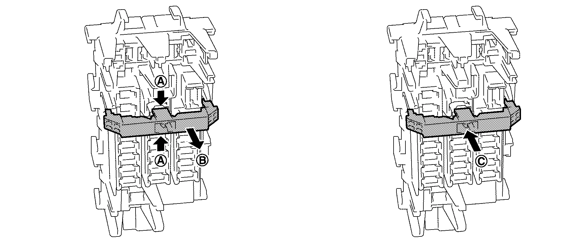
Type C
-
To place the extended storage switch in the OFF position, pull out in
direction as shown in the figure. -
To place the extended storage switch in the ON position, press in
direction as shown in the figure.
-
How To Remove Extended Storage Switch
Type A
-
Ignition switch OFF.
-
Place the extended storage switch in the OFF position.
-
Pinch tabs
and tilt to disengage the extended storage switch. Pinch tabs to remove the extended storage switch.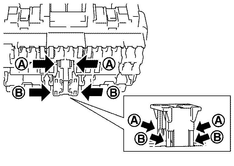
CAUTION:
For bus bar type extended storage switch, never replace bus bar with a fuse, or fuse may continually open.
NOTE:
-
Extended storage switch and fuse (or bus bar) are removed together. Remove fuse (or bus bar) from extended storage switch, if necessary.
-
Install removed fuse (or bus bar) to fuse block.
-
Extended storage switch is for transportation and storage. Reinstallation of switch is not required after removal, but fuse (or bus bar) must be reinstalled/pushed back in to activate all electrical systems and turn message off (which may be shown in meter/display).
-
Type B
-
Ignition switch OFF.
-
Place the extended storage switch in the OFF position.
-
Pinch tabs
and firmly pull out the extended storage switch in direction.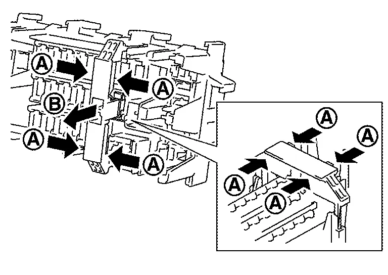
CAUTION:
For bus bar type extended storage switch, never replace bus bar with a fuse, or fuse may continually open.
NOTE:
-
Extended storage switch and fuse (or bus bar) may be removed together. Remove fuse (or bus bar) from extended storage switch, if necessary.
-
Install removed fuse (or bus bar) to fuse block.
-
Extended storage switch is for transportation and storage. Reinstallation of switch is not required after removal, but fuse (or bus bar) must be reinstalled/pushed back in to activate all electrical systems and turn message off (which may be shown in meter/display).
-
Type C
-
Ignition switch OFF.
-
Place the extended storage switch in the OFF position.
-
Pinch tabs
and firmly pull out the extended storage switch in direction.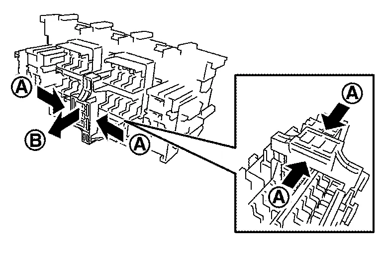
CAUTION:
For bus bar type extended storage switch, never replace bus bar with a fuse, or fuse may continually open.
NOTE:
-
Extended storage switch and fuse (or bus bar) are removed together. Remove fuse (or bus bar) from extended storage switch, if necessary.
-
Install removed fuse (or bus bar) to fuse block.
-
Extended storage switch is for transportation and storage. Reinstallation of switch is not required after removal, but fuse (or bus bar) must be reinstalled/pushed back in to activate all electrical systems and turn message off (which may be shown in meter/display).
-
 Inspection and Adjustment. Additional Service When Removing Battery Negative Terminal
Special Repair Requirement
Required Procedure After Battery Disconnection System Item Reference
Engine Control System
Idle Air Volume Learning
Description
Door & Lock
Automatic Back Door Initialization
Description
Power Window Control System
Power Window System Initialization
Description
Roof
Moonroof Memory Reset/Initialization
Sunshade Memory Reset/Initialization
Special Repair Requirement
Automatic Drive Positioner
Automatic Drive Positioner System Initialization
Refer to Owner's Manual...
 Fusible Link Inspection
Fusible Link
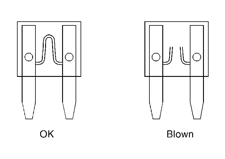
A melted fusible link can be detected either by visual inspection or by feeling with a finger tip. If its condition is questionable, use circuit tester or test lamp...
Other information:
Nissan Murano (Z52) 2015-2024 Owners Manual: Climate controlled seat switches (if so equipped)
The climate controlled seat warms up or cools down the front seat by blowingwarm or cool air from under the surface of the seat. The climate control switch is located on the center console. The climate controlled seat can be operated as follows: Place the ignition switch in the ON position...
Nissan Murano (Z52) 2015-2024 Service Manual: Component Parts. Adas Control Unit
Component Parts Location A. Center of instrument panel (view with center console assembly removed) No. Component Function 1. ADAS (Advanced Driver Assistance System) control unit Refer to ADAS Control Unit. ADAS Control Unit ADAS control unit is installed below the center console assembly...
Categories
- Manuals Home
- Nissan Murano Owners Manual
- Nissan Murano Service Manual
- Passenger compartment
- Warning lights
- Checking engine oil level
- New on site
- Most important about car
Luggage hooks

When securing items using luggage hooks located on the back of the seat or side finisher do not apply a load over more than 6.5 lbs. (29 N) to a single hook.
The luggage hooks that are located on the floor should have loads less than 110 lbs. (490 N) to a single hook.