Nissan Murano: Fuel System :: Removal and Installation / Fuel Tank. Fwd

| 1. | Fuel filler cap | 2. | Grommet | 3. | Fuel filler tube |
| 4. | Clip | 5. | Fuel tank | 6. | Fuel level sensor |
| 7. | O-ring | 8. | Lock ring | 9. | Sub fuel level assembly |
| 10. | Sub fuel level sensor | 11. | Fuel level sensor unit, fuel filter and fuel pump assembly | 12. | Fuel tank protector |
| 13. | Fuel tank strap | 14. | Clamp | 15. | Fuel filler hose |
| A. | To EVAP canister. Refer to Exploded View. | Front |
WARNING:
Be sure to read “General Precaution” when working on the fuel system. Refer to General Precaution.
 NOTE:
NOTE:
When removing components such as hoses, tubes/lines, etc., cap or plug openings to prevent fluid from spilling.
REMOVAL
Check the fuel level with the vehicle on a level surface. If the fuel gauge indicates more than the level as shown (1/2 full), drain the fuel from the fuel tank until the fuel gauge indicates a level at or below as shown (1/2 full).

-
In case the fuel pump does not operate, use the following procedure:
-
As a guide, the fuel level reaches or is less than the level on the fuel gauge as shown when approximately 27.5
 (7-1/4 US gal, 6 Imp gal) of fuel are drained from a full fuel tank.
Release fuel pressure from fuel lines. Refer to Work Procedure.
Disconnect negative battery terminal. Refer to Removal and Installation.
Unscrew fuel filler cap to release the pressure inside the fuel tank.
Remove second row seat (LH\RH). Refer to Removal and Installation.
Turn the four retainers 90 degrees to disengage the clips and remove the fuel pump inspection hole cover.
CAUTION:
Cover the immediate area surrounding the fuel pump inspection hole cover with plastic to avoid gasoline damage to carpet.
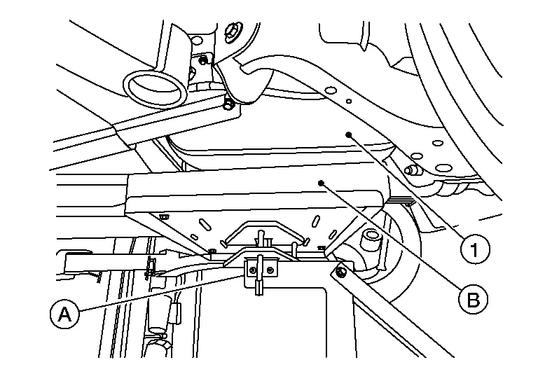
Disconnect harness connector (A) and quick connector (B).

| : Front |
Disconnect quick connector as follows:
-
Hold the sides of connector, press tabs and pull out fuel feed tube.

(A) : Pull (B) : Push in tabs -
If quick connector sticks to tube of main fuel level sensor unit, push and pull quick connectors several times until they start to move. Then disconnect them by pulling.
CAUTION:
-
Quick connector (1) can be disconnected when the tabs (F) are depressed completely. Do not twist it more than necessary.

(B) : Connection (cross-section) (D) : To under floor fuel line (E) : To fuel tank (G) : Disconnection -
Do not use any tools to disconnect quick connector.
-
Keep resin tube (C) away from heat. Be especially careful when welding near the resin tube.
-
Prevent acid liquid such as battery electrolyte, etc., from getting on resin tube.
-
Do not bend or twist resin tube during installation and disconnection.
-
Do not remove the remaining retainer (2) from hard tube (or the equivalent) (A) except when resin tube or retainer is replaced.
-
When resin tube or hard tube (or the equivalent) is replaced, also replace retainer with new one.
-
To keep the connecting portions clean and to avoid damage and foreign materials, cover them completely with plastic bags (A) or something similar.

-
Turn the four retainers 90 degrees to disengage the clips and remove the sub fuel sender inspection hole cover.
CAUTION:
Cover the immediate area surrounding the fuel pump inspection hole cover with plastic to avoid gasoline damage to carpet.
Disconnect the harness connector from the sub fuel level sensor assembly.
Remove floor undercover (LH\RH). Refer to Removal and Installation.
Remove center exhaust tube. Refer to Exploded View.
Loosen front parking brake cable and remove from equalizer. Refer to Exploded View.
Remove rear parking brake cable brackets. Refer to Exploded View.
Remove fuel tank protector.
Remove rear undercover (LH/RH). Refer to Removal and Installation.
Remove rear stabilizer bar clamp and position rear stabilizer bar aside. Refer to Exploded View.
Remove vent hose at rear side of fuel tank.
Disconnect EVAP tube at rear side of fuel tank. Refer to Exploded View.
Remove fuel filler hose at fuel filler tube side.
Support center of fuel tank (1) with suitable jack (A).
CAUTION:
Securely support the fuel tank with a piece of wood (B).
Remove fuel tank bands.
Lower suitable jack carefully to remove fuel tank while holding it by hand.
CAUTION:
Fuel tank may be in an unstable condition because of the shape of fuel tank bottom. Be sure to secure fuel tank at all times.
If replacing the fuel tank, remove sub fuel level sensor assembly, fuel level sensor unit, fuel filter and fuel pump assembly to transfer to the new fuel tank. Remove and discard O-ring. Refer to Removal and Installation.
INSTALLATION
Installation is in the reverse order of removal.
Fuel Filler Hose
-
Insert fuel filler hose to the length below:
Length : 35 mm (1.38 in) -
Be sure hose clamp is not placed on swelled area of fuel filler tube.
-
Tighten the clamp hand with the top mark (A) until the mark is on the bolt head flange.

Use the following procedure to check for fuel leaks:
Place the ignition in "ON" position (without starting the engine). Then check the connections for fuel leaks by applying fuel pressure to the fuel piping.
Start engine, raise idle and verify there are no leaks at the fuel system connections.
 Fuel Level Sensor Unit, Fuel Filter and Fuel Pump Assembly
Exploded View
1.
Lock ring
2.
O-ring
3.
Sub fuel level sensor assembly
4.
Fuel level sensor unit, fuel filter and fuel pump assembly
5...
 Evap Canister
Exploded View
EVAP CANISTER 1.
EVAP canister control pressure sensor
2.
EVAP canister
3.
Shield
4.
Clamp
5.
EVAP canister purge hose
6...
Other information:
Nissan Murano (Z52) 2015-2024 Service Manual: S Terminal Circuit
Diagnosis Procedure CAUTION: Perform diagnosis under the condition that engine cannot start by the following procedure: Remove fuel pump fuse. Crank or start the engine (where possible) until the fuel pressure is released. CHECK STARTER MOTOR MAGNETIC SWITCH CIRCUIT Ignition switch OFF...
Nissan Murano (Z52) 2015-2024 Service Manual: Repair Procedure for Pulling
Repair Sequence In general, no single bend or twist is produced in a collision. Body deformation results from a combination of bending and twisting and other types of damage.Repair should start where the damage is most deeply propagated.If concentrating only on apparent damage while overlooking the propagation of impact to the whole body, it is impossible to obtain correct body alignment...
Categories
- Manuals Home
- Nissan Murano Owners Manual
- Nissan Murano Service Manual
- Memory storage function (key-link)
- Turning the AEB system on/off
- Jacking up vehicle and removing the damaged tire
- New on site
- Most important about car
Seatback pockets

Theremaybe one or two seatback pockets located on the back of the driver and passenger seats. The pockets can be used to store maps.
WARNING