Nissan Murano: Fuel System :: Removal and Installation / Fuel Level Sensor Unit, Fuel Filter and Fuel Pump Assembly
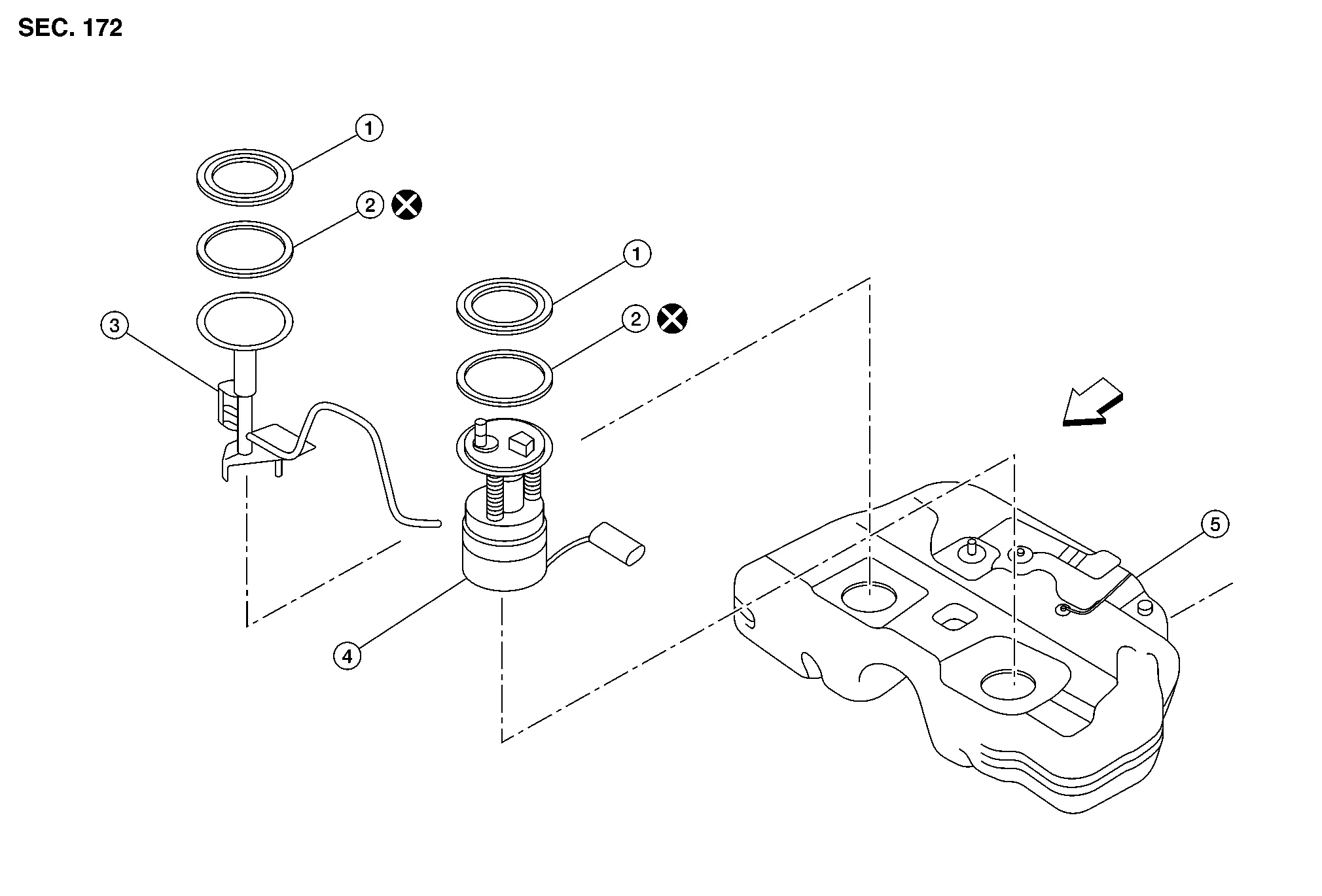
| 1. | Lock ring | 2. | O-ring | 3. | Sub fuel level sensor assembly |
| 4. | Fuel level sensor unit, fuel filter and fuel pump assembly | 5. | Fuel tank | Front |
WARNING:
Be sure to read “General Precaution” before working on the fuel system. Refer to General Precaution.
CAUTION:
Do not remove or disassemble parts unless instructed as shown.
 NOTE:
NOTE:
When removing components such as hoses, tubes/lines, etc., cap or plug openings to prevent fluid from spilling.
REMOVAL
Fuel Level Sensor Unit, Fuel Filter And Fuel Pump Assembly
Check the fuel level with the vehicle on a level surface. If the fuel gauge indicates more than the level as shown (1/2 full), drain the fuel from the fuel tank until the fuel gauge indicates a level at or below as shown (1/2 full).

-
In case the fuel pump does not operate, use the following procedure:
-
As a guide, the fuel level reaches or is less than the level on the fuel gauge as shown when approximately 27.5
 (7-1/4 US gal, 6 Imp gal) of fuel is drained from a full fuel tank.
Release fuel pressure from fuel lines. Refer to Work Procedure.
Open fuel filler lid.
Open fuel filler cap and release the pressure inside the fuel tank.
Disconnect negative battery terminal. Refer to Removal and Installation.
Remove second row seat (LH). Refer to Removal and Installation.
Turn the four retainers 90 degrees to disengage the clips and remove the fuel pump inspection hole cover.
CAUTION:
Cover the immediate area surrounding the fuel pump inspection hole cover with plastic to avoid gasoline damage to carpet.
Disconnect harness connector (A) and quick connector (B).

| : Front |
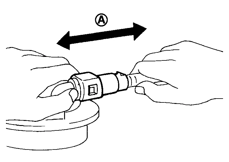
Disconnect quick connector as follows:
-
Hold the sides of connector, press tabs and pull out fuel feed tube.

(A) : Pull (B) : Push in tabs -
If quick connector sticks to tube of main fuel level sensor unit, push and pull quick connectors several times until they start to move. Then disconnect them by pulling.
CAUTION:
-
Quick connector (1) can be disconnected when the tabs (F) are depressed completely. Do not twist it more than necessary.

(B) : Connection (cross-section) (D) : To under floor fuel line (E) : To fuel tank (G) : Disconnection -
Do not use any tools to disconnect quick connector.
-
Keep resin tube (C) away from heat. Be especially careful when welding near the resin tube.
-
Prevent acid liquid such as battery electrolyte, etc., from getting on resin tube.
-
Do not bend or twist resin tube during installation and disconnection.
-
Do not remove the remaining retainer (2) from hard tube (or the equivalent) (A) except when resin tube or retainer is replaced.
-
When resin tube or hard tube (or the equivalent) is replaced, also replace retainer with new one.
-
To keep the connecting portions clean and to avoid damage and foreign materials, cover them completely with plastic bags (A) or something similar.

-
Remove lock ring from fuel level sensor, fuel filter, and fuel pump assembly.
-
Remove the lock ring using Tool (A).
Tool number (A) : — (J-45747) (shown) : KV101207S0 ( — ) 
: Front -
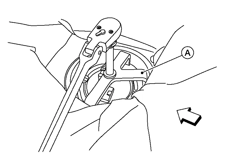
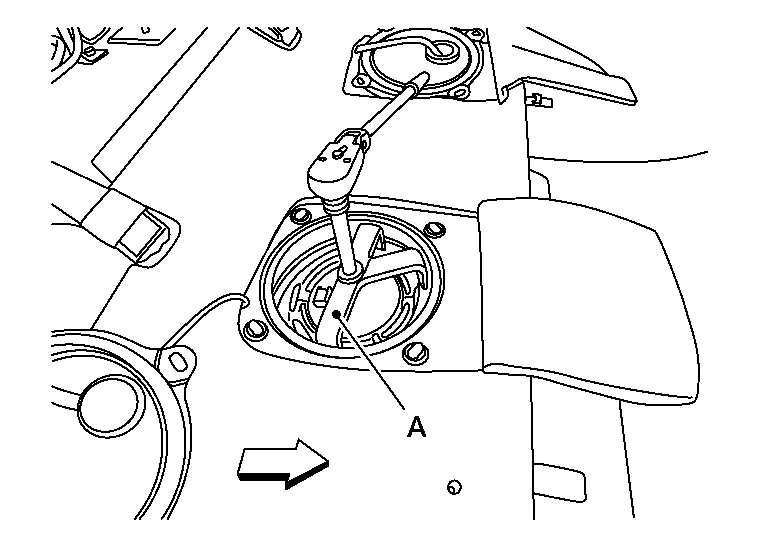
Prior to removal, observe the alignment between the fuel level sensor, fuel filter, and fuel pump assembly tabs (A) and the matching marks (C) on the fuel tank as shown. This alignment is necessary for proper installation.
(B) : Retainer mounting pawl
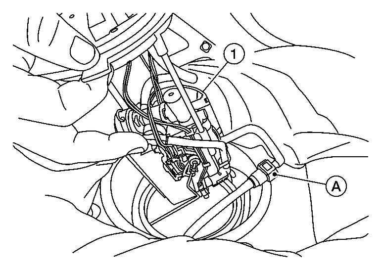
Raise fuel level sensor unit, fuel filter and fuel pump assembly (1), and disconnect fuel tube (A).
CAUTION:
-
Do not bend float arm during removal.
-
Do not pollute the inside with residue fuel. Draw out avoiding inclination by supporting with a cloth.
-
Do not cause impacts such as by dropping when handling components.
NOTE:
Tie a gasoline-resistant rope to the tip of the tube. Draw and leave the rope to the fuel tank side so that the rope can be the guide for installation.
Sub Fuel Level Sensor Assembly
Remove fuel level sensor unit, fuel filter and fuel pump assembly.
Remove second row seat (RH). Refer to Removal and Installation.
Turn the four retainers 90 degrees to disengage the clips and remove the sub fuel sensor assembly inspection hole cover.
CAUTION:
Cover the immediate area surrounding the sub fuel sensor assembly inspection hole cover with plastic to avoid gasoline damage to carpet.
Disconnect the harness connector from the sub fuel sensor assembly.
Remove lock ring from sub fuel level assembly using Tool (A).
| Tool number (A) | : — (J-45747) (shown) |
| : KV101207S0 ( — ) |
| : Front |
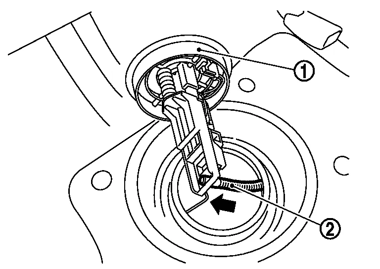
Remove sub fuel level sensor assembly (1).
CAUTION:
-
Do not disassemble a fuel tube (2) from sub fuel sensor assembly.
-
Do not bend float arm during removal.
-
Do not pollute the inside with residue fuel. Draw out avoiding inclination by supporting with a cloth.
-
Do not cause impacts such as by dropping when handling components.
INSTALLATION
Installation is in the reverse order of removal.
-
Install O-ring to fuel tank without any twists.
CAUTION:
Do not reuse O-ring.
-
Using the rope left on the fuel tank side at removal, run the fuel tube inside the fuel tank to install the sub fuel level sensor assembly to the fuel tank.
CAUTION:
-
Do not bend float arm during installation.
-
To install, fuel tube (1) must run to the front (
) of the Nissan Murano vehicle to avoid interference with the float arm (2) as shown.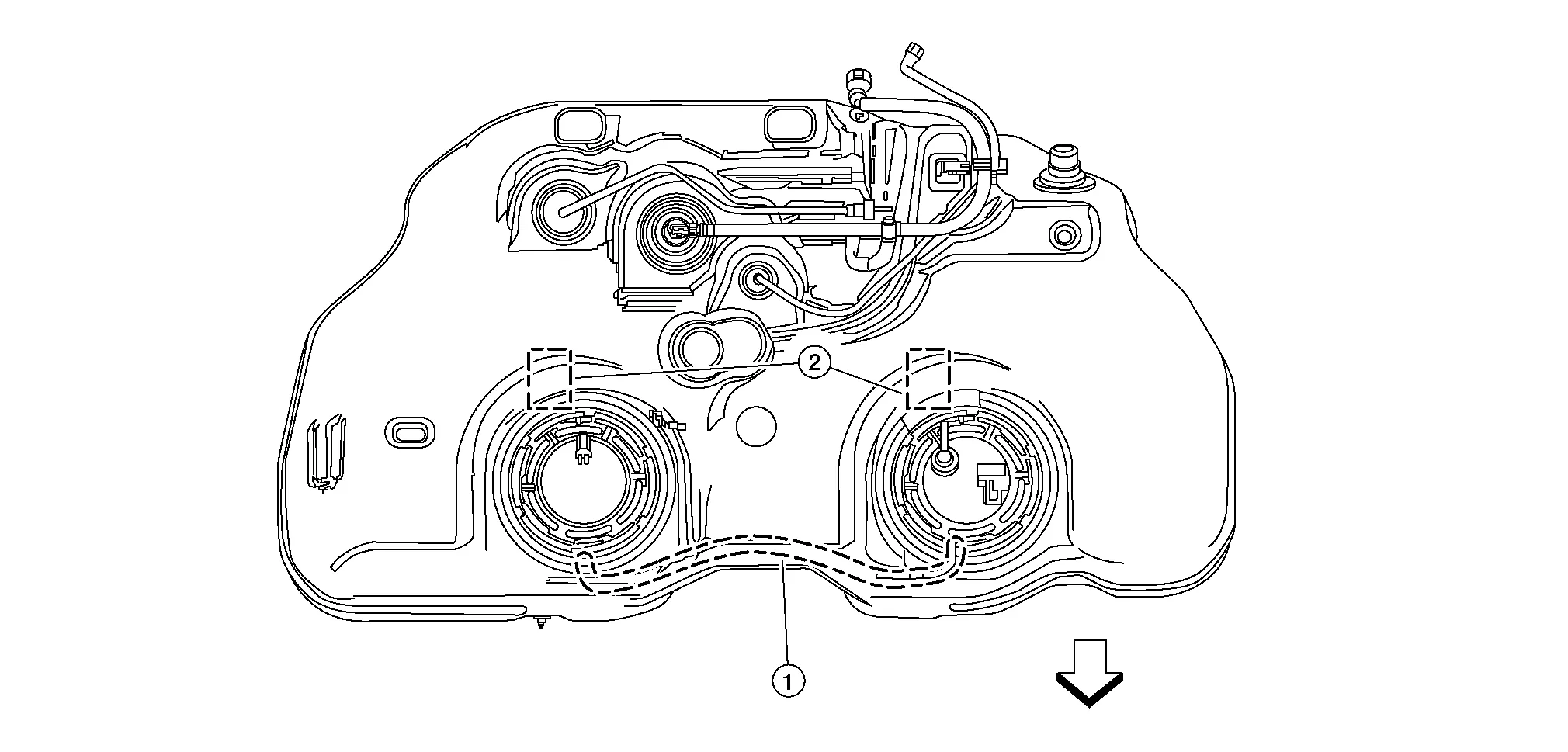
-
-
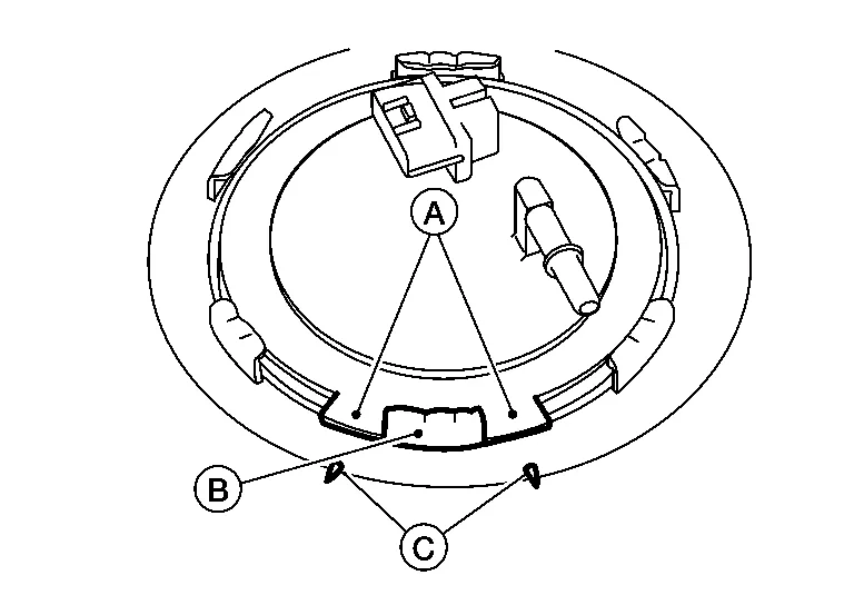
Align the tabs (A) of the fuel level sensor unit, fuel filter and fuel pump assembly (1) as shown to alignment marks (B) on the fuel tank.
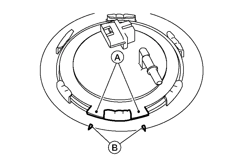
: Front NOTE:
Fuel level sensor unit, fuel filter and fuel pump assembly side of fuel tank shown.
-
Check the connection for damage or any foreign materials.
-
Align the connector with the tube then insert the connector straight into the tube until a “click” sound is heard.
-
After connecting, check that the connection is secured with the following procedures:
-
Visually confirm that the two tabs are connected to the connector.
-
Pull (A) the tube and the connector to check that they are securely connected.
-
-
Before installing inspection hole cover, check that the connecting part has no fuel leaks. Refer to Inspection.
-
Install inspection hole covers with the front mark (arrow) facing front.
-
Lock clips by turning counterclockwise.
Use the following procedure to check for fuel leaks:
With ignition in "ON" position (with engine stopped) then check connections for leaks by applying fuel pressure to fuel piping.
Start engine. Then let it idle and check that there are no fuel leaks at the fuel system connections.

 Fuel Tank. Fwd
Exploded View
1.
Fuel filler cap
2.
Grommet
3.
Fuel filler tube
4.
Clip
5.
Fuel tank
6.
Fuel level sensor
7.
O-ring
8.
Lock ring
9...
Other information:
Nissan Murano (Z52) 2015-2024 Service Manual: B242f Abd Buzzer
DTC Description DTC DETECTION LOGIC DTC No. CONSULT screen items (Trouble diagnosis content) DTC detecting condition B242F–12 ABD BUZZER (Automatic back door warning buzzer) Diagnosis condition All times Signal (terminal) Automatic back door warning buzzer signal (automatic back door control module connector terminal: 2) Threshold Automatic back door control module detects a malfunction of automatic back door warning buzzer circuit Diagnosis delay time – POSSIBLE CAUSE Harness or connectors (automatic back door warning buzzer circuit is open or shorted) Automatic back door control module FAIL-SAFE– DTC Confirmation Procedure PERFORM DTC CONFIRMATION PROCEDURE CONSULT Ignition switch ON...
Nissan Murano (Z52) 2015-2024 Owners Manual: Tire inflation pressure
Check the tire pressures (including the spare) often and always prior to long distance trips. The recommended tire pressure specifications are shown on the F.M.V.S.S./C.M.V.S.S. certification label or the Tire and Loading Information label under the “Cold Tire Pressure” heading...
Categories
- Manuals Home
- Nissan Murano Owners Manual
- Nissan Murano Service Manual
- Settings
- Rear bench seat adjustment
- Memory storage function (key-link)
- New on site
- Most important about car
Autolight system
The autolight system allows the headlights to turn on and off automatically. The autolight system can:
Turn on the headlights, front parking, tail, license plate and instrument panel lights automatically when it is dark. Turn off all the lights (except daylight running lights) when it is light. Keep all the lights on for a period of time after you place the ignition switch in the OFF position and all doors are closed.