Nissan Murano: Transmission & Driveline / Front Axle :: Unit Disassembly and Assembly. Front Drive Shaft

| 1. | Shaft with damper | 2. | Circular clip | 3. | Dust shield |
| 4. | Housing | 5. | Snap ring | 6. | Spider assembly |
| 7. | Stopper ring | 8. | Boot | 9. | Boot band |
| 10. | Joint sub-assembly |  |
Wheel side |  |
Fill with Genuine NISSAN Grease. |
DISASSEMBLY
Transaxle Side
Secure front drive shaft in a vise.
CAUTION:
When securing shaft in a vise, always use copper or aluminum plates between vise and shaft.
Remove boot bands and slide boot back.
Put matching marks on housing and shaft before separating housing.
CAUTION:
Use paint or an equivalent for matching marks. Do not scratch surfaces.
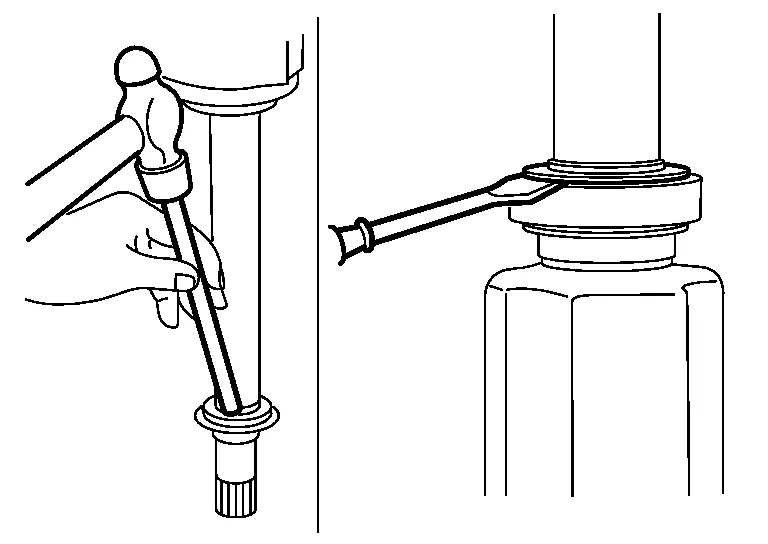
Remove stopper ring using a suitable tool.

Pull out housing.
Put matching marks (A) on spider assembly and shaft.

CAUTION:
Use paint or an equivalent for matching marks. Do not scratch surfaces.
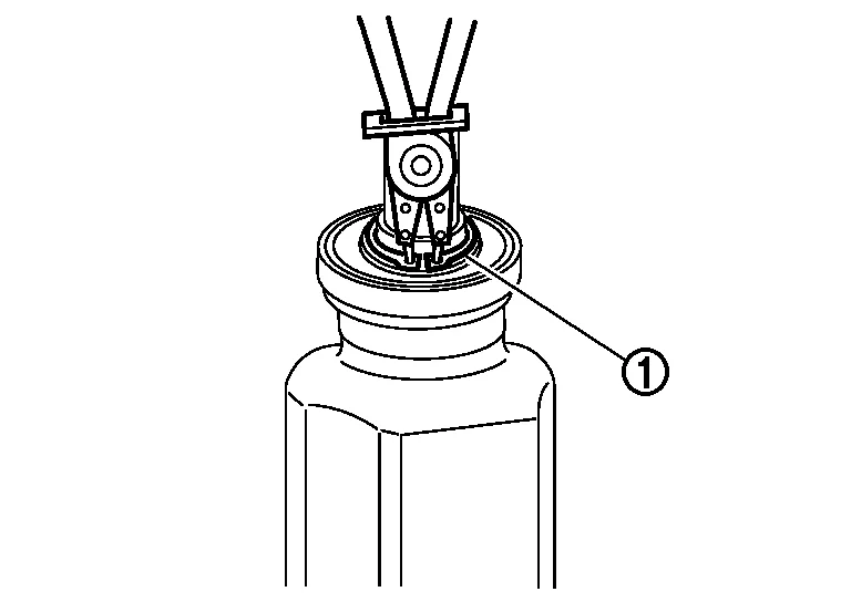
Remove snap ring (1) using a suitable tool.
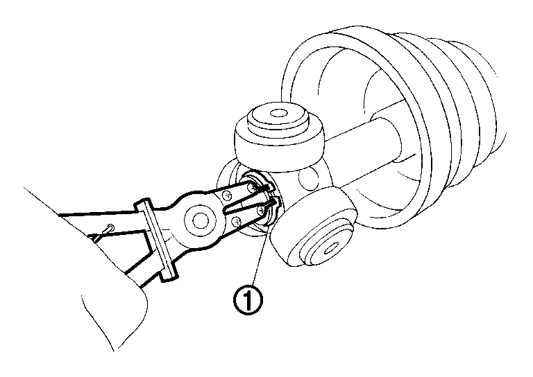
Remove spider assembly from shaft.
Remove boot from shaft.
Remove circular clip from housing.
Remove dust shield from housing.
Clean old grease off slide joint housing.
Wheel Side
Secure front drive shaft in a vise.
CAUTION:
When securing shaft in a vise, always use copper or aluminum plates between vise and shaft.
Remove boot bands and slide boot back.
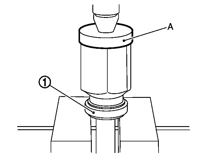
Screw a suitable tool (A) 30 mm (1.18 in) or more into threaded part of joint sub-assembly. Pull joint sub-assembly out of shaft.

CAUTION:
-
Align suitable tool (B) and drive shaft then remove joint sub-assembly by pulling directly.
-
If joint sub-assembly cannot be removed after five or more unsuccessful attempts, replace entire drive shaft.
Remove circular clip from shaft.
Remove boot from shaft.
While rotating ball cage, clean old grease off joint sub-assembly.
INSPECTION AFTER DISASSEMBLY
Shaft
-
Check shaft for runout, cracks, or other damage. Replace entire drive shaft if necessary.
Joint Sub-Assembly
-
Make sure there is no rough rotation or unusual axial looseness.
-
Make sure there is no foreign material inside joint sub-assembly.
-
Check joint sub-assembly for compression scars, cracks or fractures.
Housing
-
Make sure there are no compression scars, cracks or fractures or unusual wear of ball rolling surface.
-
Make sure there is no damage to shaft screws.
-
Make sure there is no deformation of boot installation parts.
Ball Cage
-
Make sure there are no compression scars, cracks, or fractures of sliding surface.
Steel Ball
-
Make sure there are no compression scars, cracks, fractures or unusual wear.
Inner Race
-
Check ball sliding surface for compression scars, cracks or fractures.
-
Make sure there is no damage to serrated part.
CAUTION:
If there are any irregular conditions in the component, replace entire drive shaft.
ASSEMBLY
Transaxle Side
Install new boot and new small boot band on shaft.

CAUTION:
-
Do not reuse boot and boot bands.
-
Cover drive shaft serration with protective tape (A) to prevent damage to boot during installation.
Remove protective tape wound around serrated part of shaft.
Align matching mark (A) on spider assembly (1) with matching mark on shaft (2). Install spider assembly to shaft with chamfer (B) facing shaft.
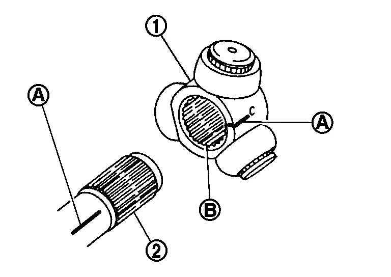
Secure spider assembly onto shaft with snap ring (1) using a suitable tool.
CAUTION:
Do not reuse snap ring.
Assemble housing onto spider assembly making sure to align matching marks made during disassembly, and fill with specified amount of new Genuine NISSAN Grease.
| Grease quantity | : Refer to Drive Shaft . |
 NOTE:
NOTE:
Always check with the Parts Department for the latest parts information.
Install new stopper ring to housing.
CAUTION:
Do not reuse stopper ring.
After installation, pull shaft to check engagement between housing and stopper ring.
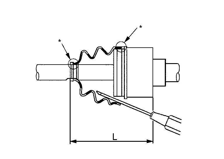
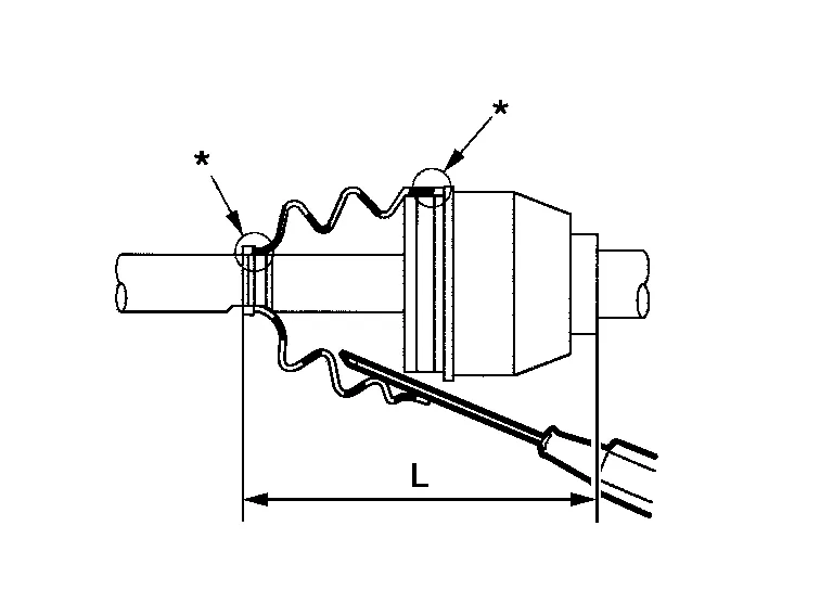
Install boot securely into grooves (indicated by "*" marks) as shown.
CAUTION:
If there is grease on boot mounting surfaces (indicated by "*" marks) on shaft or housing, boot may come off. Clean all grease from surfaces.
Make sure boot installation length (L) is length specified below. Insert a suitable tool into large end of boot. Bleed air from boot to prevent boot deformation.
| Boot installation length (L) | : Refer to Drive Shaft. |
CAUTION:
-
Boot may break if boot installation length is less than standard value.
-
Be careful that suitable tool does not contact inside surface of boot.
Install new large and small boot bands securely using Tool.

| Tool number | : KV40107300 (J-51751) |
CAUTION:
Do not reuse boot bands.
NOTE:
Secure boot band so that dimension (M) meets specification as shown.

| Dimension (M) | : Refer to Boot Bands. |
Install new dust shield to housing.
CAUTION:
Do not reuse dust shield.
Install new circular clip to housing.
CAUTION:
Do not reuse circular clip.
After installing slide joint housing and shaft, make sure boot position is correct. If boot position is not correct, remove old boot bands then reposition boot and secure with new boot bands.
CAUTION:
Do not reuse boot bands.
Wheel Side
Insert Genuine NISSAN Grease into joint sub-assembly (1) serration hole until grease begins to ooze from ball groove and serration hole.
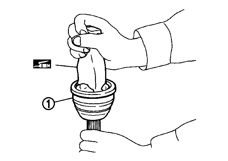
CAUTION:
After inserting grease, use a paper shop cloth to wipe off old grease that has oozed out.
NOTE:
Always check with the Parts Department for the latest parts information.
Install new boot and new small boot band on shaft.
CAUTION:
-
Do not reuse boot and boot bands.
-
Cover drive shaft serration with protective tape (A) to prevent damage to boot during installation.
Remove protective tape wound around serrated part of shaft.
Attach new circular clip to shaft. Circular clip must fit securely into shaft groove. Attach nut to joint sub-assembly. Use a suitable tool to press-fit.

WARNING:
Ensure that circular clip is properly engaged, otherwise the joint subassembly could pull away from transaxle during Nissan Murano vehicle operation resulting in loss of drive force and possible drive shaft damage, which may cause a crash and serious injury or damage the drive shaft.
Pull the joint sub-assembly in the axial direction away from transaxle assembly. Confirm that the joint sub assembly cannot be pulled out.
Insert specified amount of new Genuine NISSAN Grease listed below into housing from large end of boot.
| Grease quantity | : Refer to Drive Shaft. |
NOTE:
Always check with the Parts Department for the latest parts information.
Install boot securely into grooves (indicated by "*" marks) as shown.
CAUTION:
If there is grease on boot mounting surfaces (indicated by "*" marks) on shaft or joint sub-assembly, boot may come off. Remove all grease from surfaces.
Make sure boot installation length (L) is specified length indicated below. Insert a suitable tool into large end of boot. Bleed air from boot to prevent boot deformation.
| Boot installation length (L) | : Refer to Drive Shaft. |
CAUTION:
-
Boot may break if boot installation length is less than standard value.
-
Be careful that suitable tool does not contact inside surface of boot.
Install new large and small boot bands securely using Tool.
| Tool number | : KV40107300 (J-51751) |
CAUTION:
Do not reuse boot bands.
NOTE:
Secure boot band so that dimension (M) meets specification as shown.
| Dimension (M) | : Refer to Boot Bands. |
Attempt to rotate boot to check whether or not boot bands are securing boot. If boot is not secure, remove boot bands, reposition boot, and install new boot bands.
CAUTION:
Do not reuse boot bands.

| 1. | Support bearing retainer | 2. | Housing | 3. | Boot |
| 4. | Shaft with damper | 5. | Joint sub-assembly | 6. | Circular clip |
| 7. | Boot band | 8. | Stopper ring | 9. | Spider assembly |
| 10. | Snap ring | 11. | Support bearing | 12. | Dust shield |
| 13. | Support bearing bracket | A. | Refer to Removal and Installation. | |
Wheel side |
|
Fill with Genuine NISSAN grease. |
DISASSEMBLY
Transaxle Side
Secure shaft in a vise.
CAUTION:
When securing shaft in a vise, always use copper or aluminum plates between vise and shaft.
Remove boot bands and slide boots back.
Put matching marks on housing and shaft before separating housing.
CAUTION:
Use paint or an equivalent for matching marks. Do not scratch surfaces.
Remove stopper ring using a suitable tool.
Pull out housing.
Put matching marks (A) on spider assembly and shaft.
CAUTION:
Use paint or an equivalent for matching marks. Do not scratch surfaces.
Remove snap ring (1) using a suitable tool.
Remove spider assembly from shaft.
Remove boot from shaft.
Remove circular clip from housing.
Remove dust shield from housing.
Clean old grease off housing.
Support Bearing
Remove dust shield from housing using a suitable tool.
Remove snap ring (1) using a suitable tool.
Press support bearing off housing using a suitable tool.

Remove dust shield.
Wheel Side
Secure front drive shaft in a vise.
CAUTION:
When securing shaft in a vise, always use copper or aluminum plates between vise and shaft.
Remove boot bands and slide boot back.
Screw a suitable tool (A) 30 mm (1.18 in) or more into threaded part of joint sub-assembly. Pull joint sub-assembly out of shaft.
CAUTION:
-
Align suitable tool (B) and drive shaft then remove joint sub-assembly by pulling directly.
-
If joint sub-assembly cannot be removed after five or more unsuccessful attempts, replace entire drive shaft.
Remove circular clip from shaft.
Remove boot from shaft.
While rotating ball cage, clean old grease off joint sub-assembly.
INSPECTION AFTER DISASSEMBLY
Shaft
-
Check shaft for runout, cracks, or other damage. Replace entire drive shaft if necessary.
Joint Sub-assembly
-
Make sure there is no rough rotation or unusual axial looseness.
-
Make sure there is no foreign material inside joint sub-assembly.
-
Check joint sub-assembly for compression scars, cracks or fractures.
Housing and Spider Assembly
-
Check surfaces for scratches or wear; replace entire drive shaft if necessary.
Support Bearing
-
Make sure support bearing rolls freely and is free from noise, cracks, pitting or wear.
CAUTION:
If there are any irregular conditions of components, replace entire drive shaft.
ASSEMBLY
Transaxle Side
Install new boot and new small boot band on shaft.
CAUTION:
-
Do not reuse boot and boot bands.
-
Cover drive shaft serration with protective tape (A) to prevent damage to boot during installation.
Remove protective tape wound around serrated part of shaft.
Align matching mark (A) on spider assembly (1) with matching mark on shaft (2). Install spider assembly to shaft with chamfer (B) facing shaft.
Secure spider assembly onto shaft with snap ring (1) using a suitable tool.
CAUTION:
Do not reuse snap ring.
Assemble housing onto spider assembly making sure to align matching marks made during disassembly, and fill with specified amount of Genuine NISSAN Grease.
| Grease quantity | : Refer to Drive Shaft. |
NOTE:
Always check with the Parts Department for the latest parts information.
Install new stopper ring to housing.
CAUTION:
Do not reuse stopper ring.
After installation, pull shaft to check engagement between housing and stopper ring.
Install boot securely into grooves (indicated by "*" marks) as shown.
CAUTION:
If there is grease on boot mounting surfaces (indicated by "*" marks) on shaft or housing, boot may come off. Remove all grease from surfaces.
Make sure boot installation length (L) is length indicated below. Insert a suitable tool into large end of boot. Bleed air from boot to prevent boot deformation.
| Boot installation length (L) | : Refer to Drive Shaft. |
CAUTION:
-
Boot may break if boot installation length is less than standard value.
-
Be careful that suitable tool does not contact inside surface of boot.
Install new large and small boot bands securely using Tool.
| Tool number | : KV40107300 (J-51751) |
CAUTION:
Do not reuse boot bands.
NOTE:
Secure boot band so that dimension (M) meets specification as shown.
| Dimension (M) | : Refer to Boot Bands. |
Install new dust shield to housing.
CAUTION:
Do not reuse dust shield.
Install new circular clip to housing.
CAUTION:
Do not reuse circular clip.
After installing housing and shaft, rotate boot to check whether or not actual position is correct. If boot position is not correct, remove old boot bands then reposition boot and secure with new boot bands.
CAUTION:
Do not reuse boot bands.
Support Bearing
Install dust shield on housing.
CAUTION:
Do not reuse dust shield.
Press support bearing (1) onto housing using a suitable tool (A).
Install snap ring (1) using a suitable tool.
CAUTION:
Do not reuse snap ring.
Install dust shields.

CAUTION:
Do not reuse dust shields.
Wheel Side
Insert Genuine NISSAN Grease into joint sub-assembly serration hole until grease begins to ooze from ball groove and serration hole.
CAUTION:
After inserting grease, use a paper shop cloth to wipe off old grease that has oozed out.
NOTE:
Always check with the Parts Department for the latest parts information.
Install new boot and new small boot band on shaft.
CAUTION:
-
Do not reuse boot and boot bands.
-
Cover drive shaft serration with protective tape (A) to prevent damage to boot during installation.
Remove protective tape wound around serrated part of shaft.
Attach new circular clip to shaft. Circular clip must fit securely into shaft groove. Attach nut to joint sub-assembly. Use a suitable tool to press-fit.
WARNING:
Ensure that circular clip is properly engaged, otherwise the joint subassembly could pull away from transaxle during Nissan Murano vehicle operation resulting in loss of drive force and possible drive shaft damage, which may cause a crash and serious injury or damage the drive shaft.
Pull the joint sub-assembly in the axial direction away from transaxle assembly. Confirm that the joint sub assembly cannot be pulled out.
Insert specified amount of new Genuine NISSAN Grease listed below into housing from large end of boot.
| Grease quantity | : Refer to Drive Shaft. |
NOTE:
Always check with the Parts Department for the latest parts information.
Install boot securely into grooves (indicated by "*" marks) as shown.
CAUTION:
If there is grease on boot mounting surfaces (indicated by "*" marks) on shaft or joint sub-assembly, boot may come off. Remove all grease from surfaces.
Make sure boot installation length (L) is specified length. Insert a suitable tool into large end of boot. Bleed air from boot to prevent boot deformation.
| Boot installation length (L) | : Refer to Drive Shaft. |
CAUTION:
-
Boot may break if boot installation length is less than standard value.
-
Be careful that suitable tool does not contact inside surface of boot.
Install new large and small boot bands securely using Tool.
| Tool number | : KV40107300 (J-51751) |
CAUTION:
Do not reuse boot bands.
NOTE:
Secure boot band so that dimension (M) meets specification as shown.
| Dimension (M) | : Refer to Boot Bands. |
Attempt to rotate boot to check whether or not boot bands are securing boot. If boot is not secure, remove boot bands, reposition boot, and install new boot bands.
CAUTION:
Do not reuse boot bands.
 Front Drive Shaft
Exploded View (LH)
1.
Drive shaft
2.
Nut retainer
3.
Cotter pin
Removal and Installation (LH)
REMOVALRemove disc brake rotor. Refer to Removal and Installation...
 Front Axle :: Service Data and Specifications (sds). Service Data and Specifications (sds)
Wheel Bearing
Item Standard
Axial end play
0.05 mm (0.002 in) or less
Drive Shaft
Joint type
Wheel side
Transaxle side
Grease quantity
115 ± 10 g
(4...
Other information:
Nissan Murano (Z52) 2015-2024 Service Manual: Service Data and Specifications (sds). Service Data and Specifications (sds)
General Specification Engine model VQ35DE Drive type FWD AWD Transaxle model RE0F10J Transaxle gear ratio D position 2.413 – 0.383 R position 2.312 Final drive 4.668 Recommended fluid Refer to Fluids and Lubricants Fluid capacity liter Shift Characteristics Unit: rpm Throttle position Shift pattern CVT input speed At 40 km/h (25 MPH) At 60 km/h (37 MPH) 2/8 “D” position (Normal) 1,300 – 3,300 1,400 – 4,400 8/8 “D” position (Normal) 2,600 – 3,900 3,400 – 5,000 NOTE: Lock-up is engaged at the vehicle speed of approximately 10 km/h (6 MPH) to 60 km/h (37 MPH)...
Nissan Murano (Z52) 2015-2024 Service Manual: Steering Switches
Exploded View 1. Steering wheel 2. Cover 3. Steering switches 4. Driver air bag module A. Refer to Exploded View. Pawl Removal and Installation REMOVALNOTE: The steering switches is serviced as an assembly. Remove steering wheel...
Categories
- Manuals Home
- Nissan Murano Owners Manual
- Nissan Murano Service Manual
- Tire rotation
- Vehicle Dynamic Control (VDC) OFF switch
- System malfunction
- New on site
- Most important about car
Luggage hooks

When securing items using luggage hooks located on the back of the seat or side finisher do not apply a load over more than 6.5 lbs. (29 N) to a single hook.
The luggage hooks that are located on the floor should have loads less than 110 lbs. (490 N) to a single hook.