Nissan Murano: Body Control System :: Bcm / Ecu Diagnosis Information. Bcm
 NOTE:
NOTE:
The following table includes information (items) inapplicable to this Nissan Murano vehicle. For information (items) applicable to this vehicle, refer to CONSULT display items:
| Monitor Item | Condition | Value/Status | |
|---|---|---|---|
| ACC BATTERY SAVER | When battery saver is OFF | Under a stop | |
| ACC RLY -REQ | When BCM is not requesting accessory relay activation. | Off | |
| When BCM is requesting accessory relay activation. | On | ||
| AIR COND SW | A/C switch OFF | Off | |
| A/C switch ON | On | ||
| AIR PRESS FL | Front left tire air pressure value | kPa, kg/cm2, psi | |
| AIR PRESS FR | Front right tire air pressure value | kPa, kg/cm2, psi | |
| AIR PRESS RL | Rear left tire air pressure value | kPa, kg/cm2, psi | |
| AIR PRESS RR | Rear right tire air pressure value | kPa, kg/cm2, psi | |
| AUT CRANK TMR | Remote engine start timer duration | sec | |
| AUT CRANK TMR | When the remote engine start timer is OFF. | Off | |
| When the remote engine start timer is ON. | On | ||
| AUTO LIGHT SW | Lighting switch OFF | Off | |
| Lighting switch AUTO | On | ||
| BK DOOR STATE | Back door LOCK status | LOCK | |
| Back door UNLOCK status | UNLK | ||
| Wait with selective UNLOCK operation (5 seconds) | READY | ||
| BRAKE SW 1 | When the brake pedal is released | On | |
| When the brake pedal is depressed | Off | ||
| BRAKE SW 2 | Brake pedal released | Off | |
| Brake pedal depressed | On | ||
| BUZZER | Buzzer in combination meter OFF | Off | |
| Buzzer in combination meter ON | On | ||
| CDL LOCK SW | Door lock/unlock switch does not operate | Off | |
| Press door lock/unlock switch to the LOCK side | On | ||
| CDL UNLOCK SW | Door lock/unlock switch does not operate | Off | |
| Press door lock/unlock switch to the UNLOCK side | On | ||
| CONFRM ID ALL | The key ID does not match any key ID registered to BCM. | Yet | |
| The key ID matches any key ID registered to BCM. | DONE | ||
| CONFIRM ID4 | The key ID does not match the fourth key ID registered to BCM. | Yet | |
| The key ID matches the fourth key ID registered to BCM. | DONE | ||
| CONFIRM ID3 | The key ID does not match the third key ID registered to BCM. | Yet | |
| The key ID matches the third key ID registered to BCM. | DONE | ||
| CONFIRM ID2 | The key ID does not match the second key ID registered to BCM. | Yet | |
| The key ID matches the second key ID registered to BCM. | DONE | ||
| CONFIRM ID1 | The key ID does not match the first key ID registered to BCM. | Yet | |
| The key ID matches the first key ID registered to BCM. | DONE | ||
| CRANKING TME | Engine start timer duration. | sec | |
| CRNK PRBT TME | Engine start prohibit timer duration. | sec | |
| CRNK PRBT TMR | When the engine start prohibit timer is OFF. | Off | |
| When the engine start prohibit timer is ON. | On | ||
| DETE SW -IPDM | When selector lever is in P position | Off | |
| When selector lever is in any position other than P | On | ||
| DETE SW PWR | When BCM is not supplying power to park position switch. | Off | |
| When BCM is supplying power to park position switch. | On | ||
| DETE/CANCL SW | When selector lever is in P position | Off | |
| When selector lever is in any position other than P | On | ||
| DOOR STAT-AS | Passenger door LOCK status | LOCK | |
| Passenger door UNLOCK status | UNLK | ||
| Wait with selective UNLOCK operation (5 seconds) | READY | ||
| DOOR STAT-DR | Driver door LOCK status | LOCK | |
| Driver door UNLOCK status | UNLK | ||
| Wait with selective UNLOCK operation (5 seconds) | READY | ||
| DOOR STAT-RL | Rear left door LOCK status | LOCK | |
| Rear left door UNLOCK status | UNLK | ||
| Wait with selective UNLOCK operation (5 seconds) | READY | ||
| DOOR STAT-RR | Rear right door LOCK status | LOCK | |
| Rear right door UNLOCK status | UNLK | ||
| Wait with selective UNLOCK operation (5 seconds) | READY | ||
| DOOR SW-AS | Front door RH closed | Off | |
| Front door RH opened | On | ||
| DOOR SW-BK | Back door closed | Off | |
| Back door opened | On | ||
| DOOR SW-DR | Front door LH closed | Off | |
| Front door LH opened | On | ||
| DOOR SW-RL | Rear door LH closed | Off | |
| Rear door LH opened | On | ||
| DOOR SW-RR | Rear door RH closed | Off | |
| Rear door RH opened | On | ||
| ENGINE STATE | Engine stopped | Stop | |
| While the engine stalls | Stall | ||
| At engine cranking | Crank | ||
| Engine running | Run | ||
| FAN ON SIG | Blower motor fan switch OFF | Off | |
| Blower motor fan switch ON | On | ||
| FR FOG SW | Front fog lamp switch OFF | Off | |
| Front fog lamp switch ON | On | ||
| FR WASHER SW | Front washer switch OFF | Off | |
| Front washer switch ON | On | ||
| FR WIPER LOW | Front wiper switch OFF | Off | |
| Front wiper switch LO | On | ||
| FR WIPER HI | Front wiper switch OFF | Off | |
| Front wiper switch HI | On | ||
| FR WIPER INT | Front wiper switch OFF | Off | |
| Front wiper switch INT | On | ||
| FR WIPER STOP | Any position other than front wiper stop position | Off | |
| Front wiper stop position | On | ||
| HAZARD SW | When hazard switch is not pressed | Off | |
| When hazard switch is pressed | On | ||
| HEAD LAMP SW 1 | Headlamp switch OFF | Off | |
| Headlamp switch 1st | On | ||
| HEAD LAMP SW 2 | Headlamp switch OFF | Off | |
| Headlamp switch 1st | On | ||
| HI BEAM SW | High beam switch OFF | Off | |
| High beam switch HI | On | ||
| ID AUTHENT CANCEL TIMER | When I-Key authentication is OFF. | Under a stop | |
| ID OK FLAG | Ignition switch ACC or ON | Reset | |
| Ignition switch OFF | Set | ||
| ID REGST FL1 | ID registration of front left tire incomplete | YET | |
| ID registration of front left tire complete | DONE | ||
| ID REGST FR1 | ID registration of front right tire incomplete | YET | |
| ID registration of front right tire complete | DONE | ||
| ID REGST RL1 | ID registration of rear left tire incomplete | YET | |
| ID registration of rear left tire complete | DONE | ||
| ID REGST RR1 | ID registration of rear right tire incomplete | YET | |
| ID registration of rear right tire complete | DONE | ||
| IGN RLY1 F/B | Ignition switch OFF or ACC | Off | |
| Ignition switch ON | On | ||
| IGN RLY 1 -REQ | Ignition switch OFF or ACC | Off | |
| Ignition switch ON | On | ||
| IGN RLY 2 -REQ | Ignition switch OFF or ACC | Off | |
| Ignition switch ON | On | ||
| IGN RLY 3-REQ | When BCM is not requesting front blower motor relay activation | Off | |
| When BCM is requesting front blower motor relay activation | On | ||
| INT VOLUME | Wiper intermittent dial is in dial position 1 - 7 | 1 - 7 | |
| I-KEY OK FLAG | I-Key OFF | Key OFF | |
| I-Key ON | Key ON | ||
| KEY CYL LK-SW | Door key cylinder LOCK position | Off | |
| Door key cylinder other than LOCK position | On | ||
| KEY CYL UN-SW | Door key cylinder UNLOCK position | Off | |
| Door key cylinder other than UNLOCK position | On | ||
| KEY CYL SW-TR | Back door key cylinder UNLOCK position | Off | |
| Back door key cylinder other than UNLOCK position | On | ||
| NOT REGISTERED | BCM detects registered Intelligent Key ID, or BCM does not detect Intelligent Key ID | ID OK | |
| BCM detects non-registration Intelligent Key ID | ID NG | ||
| OPTI SEN (DTCT) | Bright outside the Nissan Murano vehicle | Close to 5V | |
| Dark outside the vehicle | Close to 0V | ||
| OPTI SEN (FILT) | Bright outside the Nissan Murano vehicle | Close to 5V | |
| Dark outside the vehicle | Close to 0V | ||
| OPTICAL SENSOR | Optical sensor ON | On | |
| Optical sensor OFF | Off | ||
| PASSING SW | Other than lighting switch PASS | Off | |
| Lighting switch PASS | On | ||
| PRBT ENG STRT | When the engine start is prohibited | Reset | |
| When the engine start is permitted | Set | ||
| PRMT ENG STRT | When the engine start is prohibited | Reset | |
| When the engine start is permitted | Set | ||
| PRMT RKE STRT | When the engine start is prohibited | Reset | |
| When the engine start is permitted | Set | ||
| PUSH SW | Return push-button ignition switch to LOCK position | Off | |
| Press push-button ignition switch | On | ||
| PUSH SW-IPDM | When engine switch (push switch) is not pressed | Off | |
| When engine switch (push switch) is pressed | On | ||
| REAR DEF SW | Rear window defogger switch OFF | Off | |
| Rear window defogger switch ON | On | ||
| REQ SW -RL |
The item is indicated, but not monitored. |
Off | |
| REQ SW -RR |
The item is indicated, but not monitored. |
Off | |
| RR WASHER SW | Rear washer switch OFF | Off | |
| Rear washer switch ON | On | ||
| RR WIPER INT | Rear wiper switch OFF | Off | |
| Rear wiper switch INT | On | ||
| RR WIPER ON | Rear wiper switch OFF | Off | |
| Rear wiper switch ON | On | ||
| RR WIPER STOP | Any position other than rear wiper stop position | Off | |
| Rear wiper stop position | On | ||
| REQ SW-AS | When passenger door request switch is not pressed | Off | |
| When passenger door request switch is pressed | On | ||
| REQ SW-BD/TR | When back door request switch is not pressed | Off | |
| When back door request switch is pressed | On | ||
| REQ SW-DR | When driver door request switch is not pressed | Off | |
| When driver door request switch is pressed | On | ||
| RKE-LOCK | When LOCK button of Intelligent Key is not pressed | Off | |
| When LOCK button of Intelligent Key is pressed | On | ||
| RKE-MODE CHG | When LOCK/UNLOCK button of Intelligent Key is not pressed and held simultaneously | Off | |
| When LOCK/UNLOCK button of Intelligent Key is pressed and held simultaneously | On | ||
| RKE OPE COUN1 | Operation frequency of Intelligent Key | 0-19 | |
| RKE OPE COUN2 | Operation frequency of Intelligent Key | 0-19 | |
| RKE-PANIC | When PANIC button of Intelligent Key is not pressed | Off | |
| When PANIC button of Intelligent Key is pressed | On | ||
| RKE PBD | When POWER BACK DOOR OPEN button of Intelligent Key is not pressed | Off | |
| When POWER BACK DOOR OPEN button of Intelligent Key is pressed | On | ||
| RKE-TR/BD | When BACK DOOR OPEN button of Intelligent Key is not pressed | Off | |
| When BACK DOOR OPEN button of Intelligent Key is pressed | On | ||
| RKE-UNLOCK | When UNLOCK button of Intelligent Key is not pressed | Off | |
| When UNLOCK button of Intelligent Key is pressed | On | ||
| SEN CANCEL SW |
This item is displayed, but not monitored. |
— | |
| SFT N-MET | When selector lever is in any position other than N | Off | |
| When selector lever is in N position | On | ||
| SFT P-MET | When selector lever is in any position other than P | Off | |
| When selector lever is in P position | On | ||
| SFT PN -IPDM | When selector lever is in any position other than P or N | Off | |
| When selector lever is in P or N position | On | ||
| SFT PN/N SW | When selector lever is in any position other than P or N | Off | |
| When selector lever is in P or N position | On | ||
| SHFTLCK SLNID PWR SPLY | When BCM is not supplying power to shift lock. | Off | |
| When BCM is supplying power to shift lock. | On | ||
| SHOCK SENSOR | Ignition switch ON (BCM is receiving normal condition signal from air bag diagnosis sensor unit) | Normal | |
| During the receiving of air bag signal from air bag diagnosis sensor unit | On | ||
| After the receiving of air bag signal from air bag diagnosis unit | Off | ||
| SHORT CRANK |
This item is displayed, but not monitored. |
— | |
| ST RLY -REQ | Ignition switch OFF or ACC | Off | |
| Ignition switch ON | On | ||
| TAIL LAMP SW | Other than lighting switch 1ST and 2ND | Off | |
| Lighting switch 1ST or 2ND | On | ||
| TCU ID | The ID of the TCU is not registered to BCM | Yet | |
| The ID of the TCU is not registered to BCM | DONE | ||
| THERMO AMP | A/C and fan ON switch OFF | Off | |
| A/C and fan ON switch ON | On | ||
| TP 4 | The ID of fourth key is not registered to BCM | Yet | |
| The ID of fourth key is registered to BCM | DONE | ||
| TP 3 | The ID of third key is not registered to BCM | Yet | |
| The ID of third key is registered to BCM | DONE | ||
| TP 2 | The ID of second key is not registered to BCM | Yet | |
| The ID of second key is registered to BCM | DONE | ||
| TP 1 | The ID of first key is not registered to BCM | Yet | |
| The ID of first key is registered to BCM | DONE | ||
| TR CANCEL SW | Trunk lid opener cancel switch OFF | Off | |
| Trunk lid opener cancel switch ON | On | ||
| TRNK/HAT MNTR | Back door closed | Off | |
| Back door opened | On | ||
| TR/BD OPEN SW | Back door opener switch OFF | Off | |
| While the back door opener switch is turned ON | On | ||
| TURN SIGNAL L | Turn signal switch OFF | Off | |
| Turn signal switch LH | On | ||
| TURN SIGNAL R | Turn signal switch OFF | Off | |
| Turn signal switch RH | On | ||
| UNLK SEN-DR | Driver door UNLOCK status | Off | |
| Driver door LOCK status | On | ||
| VEH SPEED 1 | While driving, equivalent to speedometer reading | mph, km/h | |
| VEH SPEED 2 | While driving, equivalent to speedometer reading | mph, km/h | |
| WARNING LAMP | Low tire pressure warning lamp in combination meter OFF | Off | |
| Low tire pressure warning lamp in combination meter ON | On | ||
NOTE:
The Signal Tech II Tool [– (J-50190)] can be used to perform the following functions. Refer to the Signal Tech II User Guide for additional information.
-
Activate and display TPMS transmitter IDs
-
Display tire pressure reported by the TPMS transmitter
-
Read TPMS DTCs
-
Register TPMS transmitter IDs
-
Check Intelligent Key relative signal strength
-
Confirm Nissan Murano vehicle Intelligent Key antenna signal strength
TERMINAL LAYOUT
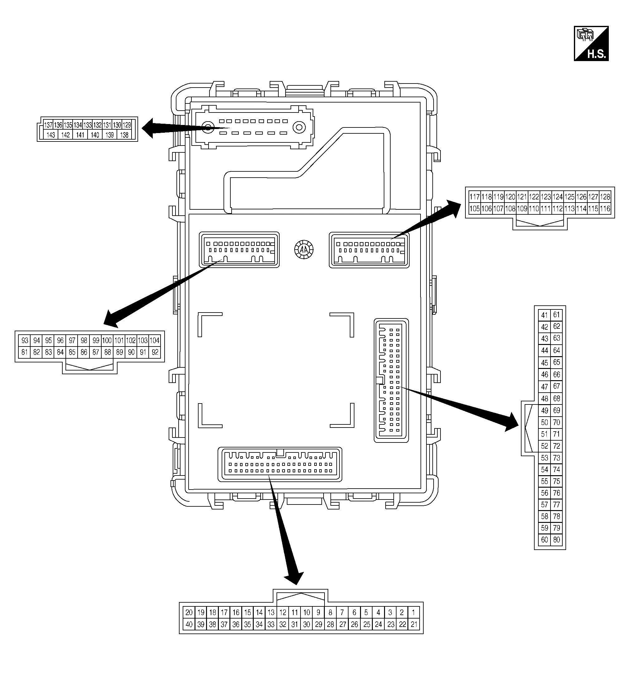
PHYSICAL VALUES
|
Terminal No. (Wire color) | Description | Condition |
Value (Approx.) | |||
|---|---|---|---|---|---|---|
| Signal name | Input/ Output | |||||
| (+) | (-) | |||||
|
1 (G) |
Ground | Push-button ignition switch signal | Input | Push-button ignition switch | Pressed | 0V |
| Not pressed | Battery voltage | |||||
|
3 (W) |
Ground | Optical sensor power supply | Output | Ignition switch | OFF | 0V |
| ACC or ON | 5V | |||||
|
4 (G) |
Ground | Optical sensor signal | Input | Ignition switch ON | When outside of the Nissan Murano vehicle is bright | Close to 5V |
| When outside of the vehicle is dark | Close to 0V | |||||
|
10 (W) |
Ground | Combination switch input 5 | Input | Combination switch | OFF | 0V |
| TURN RH |
|
|||||
| HEADLAMP 1 | ||||||
| HI BEAM | ||||||
| TAIL LAMP | ||||||
|
11 (BG) |
Ground | Combination switch input 4 | Input | Combination switch | OFF | 0V |
| TURN LH |
|
|||||
| PASSING | ||||||
| HEADLAMP 2 | ||||||
| FR FOG | ||||||
|
12 (R) |
Ground | Combination switch input 3 | Input | Combination switch | OFF | 0V |
| FR WIPER LOW |
|
|||||
| FR WIPER INT/AUTO | ||||||
| AUTO LIGHT | ||||||
|
13 (G) |
Ground | Combination switch input 2 | Input | Combination switch | OFF | 0V |
| FR WASHER |
|
|||||
| RR WASHER | ||||||
| INT VOLUME 3 | ||||||
| RR WIPER ON | ||||||
|
14 (P) |
Ground | Combination switch input 1 | Input | Combination switch | OFF | 0V |
| FR WIPER HI |
|
|||||
| INT VOLUME 1 | ||||||
| RR WIPER INT | ||||||
| INT VOLUME 2 | ||||||
|
17 (R) |
Ground | Optical sensor ground | Input | Ignition switch ON | 0V | |
|
18 (V) |
Ground | Security indicator signal | Output | Security indicator | ON | 0V |
| Blinking |
|
|||||
| OFF | Battery voltage | |||||
|
20 (W) |
Ground | CVT shift selector (detent switch) signal | Input | CVT shift selector | P position | 0V |
| Any position other than P | Battery voltage | |||||
|
25 (W) |
Ground | Battery power supply (brake switch) | Input | — | Battery voltage | |
|
26 (L) |
Ground | Battery power supply | Input | Ignition switch OFF | Battery voltage | |
|
27 (G) |
Ground | Stop lamp switch signal | Input | Stop lamp switch | OFF (brake pedal is not depressed) | 0V |
| ON (brake pedal is depressed) | Battery voltage | |||||
|
30 (P) |
Ground | Door unlock sensor signal | Input | Front door LH | LOCK status |
|
| UNLOCK status | 0V | |||||
|
32 (Y) |
Ground | Rear window defogger ON signal | Input | Rear window defogger switch | OFF | 5V |
| ON | 0V | |||||
|
36 (W) |
Ground | Hazard switch signal | Input | Hazard switch | Pressed | 0 V |
| Not pressed |
|
|||||
|
39 (G) |
Ground | Transmission range switch signal | Input | CVT shift selector | P or N position | Battery voltage |
| Except P and N positions | 0V | |||||
|
45 (BR) |
Ground | Mood lamp control | Output | Ignition switch | ON | Battery voltage |
| OFF | 0V | |||||
|
46 (P) |
Ground | Map lamp RH control | Output | Map lamp switch RH | Pressed | Battery voltage |
| Not pressed | 0V | |||||
|
47 (BG) |
Ground | Map lamp LH control | Output | Map lamp switch LH | Pressed | Battery voltage |
| Not pressed | 0V | |||||
|
48 (P) |
Ground | Push-button ignition switch illumination power supply | Output | Push-button ignition switch illumination | ON | 5.5V |
| OFF | 0V | |||||
|
511 (L) |
Ground | Motion activated back door control unit serial communication. | Input/ Output | — | — | |
|
522 (W) |
Ground | Audio dongle signal | Input/Output | Ignition switch OFF | 5V | |
|
54 (W) |
Ground | Power window LIN communication | Input/Output | Ignition switch | ON |
|
| OFF or ACC | 0V | |||||
|
59 (P) |
Ground | CAN-Low | Input/ Output | — | — | |
|
60 (L) |
Ground | CAN-High | Input/ Output | — | — | |
|
61 (BG) |
Ground | Rear defogger relay control | Output | Rear window defogger | Active | 0V |
| Not activated | Battery voltage | |||||
|
62 (W) |
Ground | Starter relay control | Output | Ignition switch ON | When CVT shift selector is in P or N position and the brake is depressed | 0V |
| When CVT shift selector is in P or N position and the brake is not depressed | Battery voltage | |||||
|
64 (P) |
Ground | Intelligent Key warning buzzer control | Output | Intelligent Key warning buzzer | Sounding | 0V |
| Not sounding | Battery voltage | |||||
|
66 (W) |
Ground | Front blower motor relay control | Output | Ignition switch | OFF or ACC | 0V |
| ON | Battery voltage | |||||
|
67 (G) |
Ground | Ignition relay-2 control | Output | Ignition switch | OFF or ACC | 0V |
| ON | Battery voltage | |||||
|
69 (G) |
Ground | CVT shift selector (detent switch) power supply | Output | — | Battery voltage | |
|
70 (P) |
Ground | Ignition relay-1 control | Output | Ignition switch | OFF or ACC | Battery voltage |
| ON | 0V | |||||
|
71 (R) |
Ground | Front outside handle assembly LH (request switch) signal | Input | Front outside handle assembly LH (request switch) | ON (pressed) | 0V |
| OFF (not pressed) |
|
|||||
|
72 (G) |
Ground | Front outside handle assembly RH (request switch) signal | Input | Front outside handle assembly RH (request switch) | ON (pressed) | 0V |
| OFF (not pressed) |
|
|||||
|
75 (BG) |
Ground | Combination switch output 5 | Output | Combination switch | OFF |
|
| INT VOLUME 2 |
|
|||||
| RR WIPER ON | ||||||
| FR FOG | ||||||
|
76 (P) |
Ground | Combination switch output 4 | Output | Combination switch | OFF |
|
| RR WIPER INT |
|
|||||
| INT VOLUME 3 | ||||||
| AUTO LIGHT | ||||||
| TAIL LAMP | ||||||
|
77 (R) |
Ground | Combination switch output 3 | Output | Combination switch | OFF |
|
| INT VOLUME 1 |
|
|||||
| RR WASHER | ||||||
| HEADLAMP 2 | ||||||
| HI BEAM | ||||||
|
78 (G) |
Ground | Combination switch output 2 | Output | Combination switch | OFF |
|
| FR WIPER HI |
|
|||||
| FR WIPER INT/AUTO | ||||||
| PASSING | ||||||
| HEADLAMP 1 | ||||||
|
79 (W) |
Ground | Combination switch output 1 | Output | Combination switch | OFF |
|
| FR WASHER |
|
|||||
| FR WIPER LOW | ||||||
| TURN LH | ||||||
| TURN RH | ||||||
|
80 (R) |
Ground | Back door opener switch (opener switch) signal | Output | Back door opener switch (opener switch) | Open (back door actuator is activated) | 0V |
| Close (back door actuator is not activated) | Battery voltage | |||||
|
81 (L) |
Ground | Battery power supply (rear wiper) | Input | Ignition switch OFF | Battery voltage | |
|
82 (W) |
Ground | Rear door switch LH signal | Input | Rear door switch LH | OFF (when rear door LH closes) |
|
| ON (when rear door LH opens) | 0V | |||||
|
83 (BG) |
Ground | Back door opener switch (request switch) signal | Input | Back door opener switch (request switch) | ON (pressed) | 0V |
| OFF (not pressed) | Battery voltage | |||||
|
84 (BR) |
Ground | Rear wiper stop position signal | Input | Ignition switch ON | Rear wiper stop position | Battery voltage |
| Any position other than rear wiper stop position | 0V | |||||
|
85 (BG) |
Ground | Luggage room lamp control | Output | Luggage room lamp | ON | 0V |
| OFF | Battery voltage | |||||
|
89 (LG) |
Ground | Back-up lamp power supply | Output | Ignition switch ON | R position |
|
| Any position other than R | 0V | |||||
|
913 (BR) |
Ground | Back door lock assembly power supply | Output | Back door opener switch (opener switch) | OFF | 0V |
| ON | Battery voltage | |||||
|
92 (R) |
Ground | Rear RH turn signal power supply | Output | Ignition switch ON | Turn signal switch OFF | 0V |
| Turn signal switch RH |
|
|||||
|
93 (R) |
Ground | Rear door switch RH signal | Input | Rear door switch RH | OFF (when rear door RH closes) |
|
| ON (when rear door RH opens) | 0V | |||||
|
94 (G) |
Ground | Front door switch RH signal | Input | Front door switch RH | OFF (when front door RH closes) |
|
| ON (when front door RH opens) | 0V | |||||
|
95 (V) |
Ground | Rear wiper motor power supply | Output | Rear wiper motor | OFF (stopped) | 0V |
| ON (activated) | Battery voltage | |||||
|
96 (BG) |
Ground | Front door switch LH signal | Input | Front door switch LH | OFF (front door LH CLOSE) |
|
| ON (front door LH OPEN) | 0V | |||||
|
97 (W) |
Ground | Back door lock assembly (back door switch) signal | Input | Back door lock assembly (back door switch) | OFF (back door is closed) |
|
| ON (back door is open) | 0V | |||||
|
984 (SB) |
Ground | Door mirror LH turn signal power supply | Output | Ignition switch ON | Turn signal switch OFF | 0V |
| Turn signal switch LH |
|
|||||
|
99 (P) |
Ground | Inside key antenna (luggage room) B | Output | Ignition switch OFF | When Intelligent Key is in the passenger compartment |
|
| When Intelligent Key is not in the passenger compartment |
|
|||||
|
100 (W) |
Ground | Inside key antenna (luggage room) A | Output | Ignition switch OFF | When Intelligent Key is in the passenger compartment |
|
| When Intelligent Key is not in the passenger compartment |
|
|||||
|
101 (R) |
Ground | Outside key antenna (rear bumper) B | Output | When the back door request switch is operated with ignition switch OFF | When Intelligent Key is in the antenna detection area |
|
| When Intelligent Key is not in the antenna detection area |
|
|||||
|
102 (G) |
Ground | Outside key antenna (rear bumper) A | Output | When the back door request switch is operated with ignition switch OFF | When Intelligent Key is in the antenna detection area |
|
| When Intelligent Key is not in the antenna detection area |
|
|||||
|
103 (BG) |
Ground | Rear turn signal LH power supply | Output | Ignition switch ON | Turn signal switch OFF | 0V |
| Turn signal switch LH |
|
|||||
|
1044 (LG) |
Ground | Door mirror RH turn signal power supply | Output | Ignition switch ON | Turn signal switch OFF | 0V |
| Turn signal switch RH |
|
|||||
|
105 (LG) |
Ground | Front turn signal RH power supply | Output | Ignition switch ON | Turn signal switch OFF | 0V |
| Turn signal switch RH |
|
|||||
|
107 (W) |
Ground | Push-button ignition switch illumination control | Output | Push-button ignition switch illumination | OFF | 0V |
|
When the illumination brightening/dimming level is in the neutral position ON |
|
|||||
|
108 (G) |
Ground | Shift lock solenoid power supply | Input | CVT shift selector | P position | 0V |
| Any position other than P | Battery voltage | |||||
|
109 (G) |
Ground | Reverse signal | Output | Ignition switch ON | R position | Battery voltage |
| Any position other than R | 0V | |||||
|
111 (LG) |
Ground | Push-button ignition switch ACC/ON control | Output | Push-button ignition switch ACC/ON indicator | OFF | Battery voltage |
| ACC or ON | 0V | |||||
|
113 (L) |
Ground | Accessory relay-1 control | Output | Ignition switch | OFF | 0V |
| ACC or ON | Battery voltage | |||||
|
114 (W) |
Ground | Front outside handle assembly RH (outside key antenna) A | Output | When the front door RH request switch is operated with ignition switch OFF | When Intelligent Key is in the antenna detection area |
|
| When Intelligent Key is not in the antenna detection area |
|
|||||
|
115 (BG) |
Ground | Front outside handle assembly RH (outside key antenna) B | Output | When the front door RH request switch is operated with ignition switch OFF | When Intelligent Key is in the antenna detection area |
|
| When Intelligent Key is not in the antenna detection area |
|
|||||
|
116 (W) |
Ground | Inside key antenna (console) A | Output | Ignition switch OFF | When Intelligent Key is in the passenger compartment |
|
| When Intelligent Key is not in the passenger compartment |
|
|||||
|
117 (SB) |
Ground | Left turn signal lamp LH power supply | Output | Ignition switch ON | Turn signal switch OFF | 0V |
| Turn signal switch LH |
|
|||||
|
119 (R) |
Ground | Remote keyless entry receiver communication | Input/Output | Ignition switch ON | Standby state |
|
| When receiving the signal from the transmitter |
|
|||||
|
121 (G) |
Ground | Front outside handle assembly LH (outside key antenna) B | Output | When the front door LH request switch is operated with ignition switch OFF | When Intelligent Key is in the antenna detection area |
|
| When Intelligent Key is not in the antenna detection area |
|
|||||
|
122 (GR) |
Ground | Front outside handle assembly LH (outside key antenna) A | Output | When the front door LH request switch is operated with ignition switch OFF | When Intelligent Key is in the antenna detection area |
|
| When Intelligent Key is not in the antenna detection area |
|
|||||
|
126 (P) |
Ground | NATS antenna amp. B | Input/Output | During waiting | Intelligent Key backside is contacted to push-button ignition switch, ignition switch ON. | Just after pressing push-button ignition switch, pointer of analog volt meter should move. |
|
127 (BG) |
Ground | NATS antenna amp. A | Input/Output | During waiting | Intelligent Key backside is contacted to push-button ignition switch, ignition switch ON. | Just after pressing push-button ignition switch pointer of analog volt meter should move. |
|
128 (R) |
Ground | Inside key antenna (console) B | Output | Ignition switch OFF | When Intelligent Key is in the passenger compartment |
|
| When Intelligent Key is not in the passenger compartment |
|
|||||
|
129 (SB) |
Ground | Battery saver output | Output | After passing the interior room lamp battery saver operation time | 0V | |
| Any other time after passing the interior room lamp battery saver operation time | Battery voltage | |||||
|
130 (LG) |
Ground | Front door RH (UNLOCK) control | Output | Front door RH | UNLOCK (actuator is activated) | Battery voltage |
| Other than UNLOCK (actuator is not activated) | 0V | |||||
|
131 (W) |
Ground | Battery power supply | Input | Ignition switch OFF | Battery voltage | |
|
132 (BR) |
Ground | Rear door (LOCK) control | Output | All doors | LOCK (actuator is activated) | Battery voltage |
| Other than LOCK (actuator is not activated) | 0V | |||||
|
133 (Y) |
Ground | Rear door (UNLOCK) control | Output | Rear door RH and rear door LH | UNLOCK (actuator is activated) | Battery voltage |
| Other than UNLOCK (actuator is not activated) | 0V | |||||
|
134 (GR) |
Ground | Ground | — | Ignition switch ON | 0V | |
|
135 (L) |
Ground | Front door (LOCK) control | Output | All doors | LOCK (actuator is activated) | Battery voltage |
| Other than LOCK (actuator is not activated) | 0V | |||||
|
136 (LG) |
Ground | Room lamp control | Output | Interior room lamp | OFF | Battery voltage |
| ON | 0V | |||||
|
137 (V) |
Ground | Front door LH (UNLOCK) control | Output | Front door LH | UNLOCK (actuator is activated) | Battery voltage |
| Other than UNLOCK (actuator is not activated) | 0V | |||||
|
138 (V) |
Ground | Battery power supply (rear door) | Input | Ignition switch OFF | Battery voltage | |
|
139 (L) |
Ground | Battery power supply | Input | Ignition switch OFF | Battery voltage | |
|
140 (BR) |
Ground | Ignition power supply output | Output | Ignition switch ON | Battery voltage | |
|
141 (Y) |
Ground | Battery power supply output | Output | Ignition switch OFF | Battery voltage | |
|
142 (Y) |
Ground | Battery power supply (front door) | Input | Ignition switch OFF | Battery voltage | |
|
143 (GR) |
Ground | Ground | — | Ignition switch ON | 0V | |


1: With automatic back door
2: For Canada
3: Without automatic back door
4: With turn signal in mirror
| Display contents of CONSULT | Fail-safe | Cancellation |
|---|---|---|
| B2192: ID DISCORD BCM-ECM | Inhibit engine cranking | Erase DTC |
| B2193: CHAIN OF BCM-ECM | Inhibit engine cranking | Erase DTC |
| B2195: ANTI-SCANNING | Inhibit engine cranking | Ignition switch ON → OFF |
| B2560: STARTER CONT RELAY | Inhibit engine cranking |
500 ms after the following CAN signal communication status has become consistent:
|
| B2562: LOW VOLTAGE | Inhibit engine cranking | 100 ms after the power supply voltage increases to more than 8.8 V |
| B2608: STARTER RELAY | Inhibit engine cranking |
500 ms after the following signal communication status becomes consistent:
|
| B260A: IGNITION RELAY | Inhibit engine cranking |
500 ms after the following conditions are fulfilled:
|
| B260F: ENG STATE SIG LOST | Maintains the power supply position attained at the time of DTC detection |
When any of the following conditions is fulfilled:
|
| B261E: VHEICLE TYPE | Inhibit engine cranking | BCM initialization |
If some DTCs are displayed at the same time, perform inspections one by one based on the following priority chart:
| Priority | DTC |
|---|---|
| 1 |
|
| 2 |
|
| 3 |
|
| 4 |
|
| 5 |
|
| 6 |
|
| 7 | B259A: ROOM LAMP FUSE BLOWN |
NOTE:
Details of time display
-
CRNT: Displays when there is a malfunction now or after returning to the normal condition until placing ignition switch OFF → ON again.
-
1 - 39: Displayed if any previous malfunction is present when current condition is normal. It increases like 1 → 2 → 3...38 → 39 after returning to the normal condition whenever ignition is placed OFF → ON. The counter remains at 39 even if the number of cycles exceeds it. It is counted from 1 again when placing ignition switch OFF → ON after returning to the normal condition if the malfunction is detected again.
| CONSULT display | Fail-safe | Intelligent Key warning lamp ON | Tire pressure monitor warning lamp ON | Reference page |
|---|---|---|---|---|
|
No DTC is detected. Further testing may be required. |
— | — | — | — |
| U1000: CAN COMM CIRCUIT | — | — | — | DTC Description |
| U1010: CONTROL UNIT(CAN) | — | — | — | DTC Description |
| U0415: Nissan Murano Vehicle SPEED | — | — | — | DTC Description |
| B2192: ID DISCORD BCM-ECM | × | — | — | DTC Description |
| B2193: CHAIN OF BCM-ECM | × | — | — | DTC Description |
| B2195: ANTI-SCANNING | × | — | — | DTC Description |
| B2196: DONGLE NG | — | — | — | DTC Description |
| B2198: NATS ANTENNA AMP | — | — | — | DTC Description |
| B2555: STOP LAMP | — | — | — | DTC Description |
| B2556: PUSH-BTN IGN SW | — | × | — | DTC Description |
| B2557: Nissan Murano Vehicle SPEED | — | × | — | DTC Description |
| B2560: STARTER CONT RELAY | × | × | — | DTC Description |
| B2562: LOW VOLTAGE | × | — | — | DTC Description |
| B259A: ROOM LAMP FUSE BLOWN | — | — | — | DTC Description |
| B2601: SHIFT POSITION | — | × | — | DTC Description |
| B2602: SHIFT POSITION | — | × | — | DTC Description |
| B2603: SHIFT POSI STATUS | — | × | — | DTC Description |
| B2604: PNP/CLUTCH SW | — | × | — | DTC Description |
| B2605: PNP/CLUTCH SW | — | × | — | DTC Description |
| B2608: STARTER RELAY | × | × | — | DTC Description |
| B260A: IGNITION RELAY | × | × | — | DTC Description |
| B260F: ENG STATE SIG LOST | × | × | — | DTC Description |
| B2614: BCM | — | — | — | DTC Description |
| B2615: BCM | — | — | — | DTC Description |
| B2616: BCM | — | — | — | DTC Description |
| B2618: BCM | — | — | — | DTC Description |
| B261A: PUSH-BTN IGN SW | — | × | — | DTC Description |
| B261B: RES ENG RUN STUCK MALFUNC | — | — | — | DTC Description |
| B261E: VHEICLE TYPE | × | × (Turn ON for 15 seconds) | — | DTC Description |
| B2622: INSIDE ANTENNA | — | — | — | DTC Description |
| B2623: INSIDE ANTENNA | — | — | — | DTC Description |
| B2627: OUTSIDE ANTENNA | — | — | — | DTC Description |
| B2628: OUTSIDE ANTENNA | — | — | — | DTC Description |
| B26F1: IGN RELAY OFF | — | — | — | DTC Description |
| B26F2: IGN RELAY ON | — | — | — | DTC Description |
| B26F3: START CONT RLY ON | — | — | — | DTC Description |
| B26F4: START CONT RLY OFF | — | — | — | DTC Description |
| B26F6: BCM | — | — | — | DTC Description |
| B26F7: BCM | — | — | — | DTC Description |
| B26FC: KEY REGISTRATION | — | — | — | DTC Description |
| B26FD: SHFT LCK SLNOID INSID F/B MLFNC | — | — | — | DTC Description |
| B26FE: HOOD SW CAN DIAG ERROR | — | — | — | DTC Description |
| B26FF: INTELLIGENT TUNER COMM ERR | — | — | — | DTC Description |
| C1704: LOW PRESSURE FL | — | — | × | DTC Description |
| C1705: LOW PRESSURE FR | — | — | × | DTC Description |
| C1706: LOW PRESSURE RR | — | — | × | DTC Description |
| C1707: LOW PRESSURE RL | — | — | × | DTC Description |
| C1708: [NO DATA] FL | — | — | × | DTC Description |
| C1709: [NO DATA] FR | — | — | × | DTC Description |
| C1710: [NO DATA] RR | — | — | × | DTC Description |
| C1711: [NO DATA] RL | — | — | × | DTC Description |
| C1716: [PRESSDATA ERR] FL | — | — | × | DTC Description |
| C1717: [PRESSDATA ERR] FR | — | — | × | DTC Description |
| C1718: [PRESSDATA ERR] RR | — | — | × | DTC Description |
| C1719: [PRESSDATA ERR] RL | — | — | × | DTC Description |
| C1729: VHCL SPEED SIG ERR | — | — | × | DTC Description |
| C1730: FLAT TIRE FL | — | — | × | DTC Description |
| C1731: FLAT TIRE FR | — | — | × | DTC Description |
| C1732: FLAT TIRE RR | — | — | × | DTC Description |
| C1733: FLAT TIRE RL | — | — | × | DTC Description |
| C1734: CONTROL UNIT | — | — | × | DTC Description |
| C1735: IGN CIRCUIT OPEN | — | — | × | DTC Description |
| C1761: TEMPERATURE DATA FL | — | — | — | DTC Description |
| C1762: TEMPERATURE DATA FR | — | — | — | DTC Description |
| C1763:TEMPERATURE DATA RR | — | — | — | DTC Description |
| C1764: TEMPERATURE DATA RL | — | — | — | DTC Description |
| C1769: CONFIG SETTING | — | — | — | DTC Description |
| C1770: G SENSOR FAIL FL | — | — | — | DTC Description |
| C1771: G SENSOR FAIL FR | — | — | — | DTC Description |
| C1772: G SENSOR FAIL RR | — | — | — | DTC Description |
| C1773: G SENSOR FAIL RL | — | — | — | DTC Description |
 Air Pressure Monitor
CONSULT Function (BCM-AIR PRESSURE MONITOR)
ECU IDENTIFICATIONThe BCM part number is displayed.SELF DIAGNOSTIC RESULTRefer to DTC Index.DATA MONITOR Monitor Item [Unit] Description
AIR PRESS FL [kPa, kg/cm2 or Psi]
Indicates air pressure of front LH tire...

Other information:
Nissan Murano (Z52) 2015-2024 Service Manual: Transfer Cover Oil Seal
Exploded View 1. Transfer case assembly 2. Drive shaft oil seal 3. Transfer cover oil seal Removal and Installation REMOVALRemove the front drive shaft (RH). Refer to Removal & Installation. Remove bolts and remove front drive shaft support bracket (RH)...
Nissan Murano (Z52) 2015-2024 Service Manual: Cvt Control System
Component Parts Location CVT shift selector assembly Combination meter Behind of combination meter Engine room (RH side) Engine room (LH side) Transaxle assembly COMPONENT DESCRIPTION No. Component Function Manual mode switch Manual Mode Switch Combination meter Mainly transmits the following signal to TCM via CAN communication Manual mode signal Non-manual mode signal Manual mode shift up signal Manual mode shift down signal Mainly receives the following signals from TCM via CAN communication...
Categories
- Manuals Home
- Nissan Murano Owners Manual
- Nissan Murano Service Manual
- Jacking up vehicle and removing the damaged tire
- Passenger compartment
- Intelligent Forward Collision Warning (I-FCW)
- New on site
- Most important about car
LATCH (Lower Anchors and Tethers for CHildren) system

LATCH system lower anchor locations - bench seat
Your vehicle is equipped with special anchor points that are used with LATCH system compatible child restraints. This system may also be referred to as the ISOFIX or ISOFIX compatible system. With this system, you do not have to use a vehicle seat belt to secure the child restraint unless the combined weight of the child and child restraint exceeds 65 lbs. (29.5 kg). If the combined weight of the child and child restraint is greater than 65 lbs. (29.5 kg), use the vehicle’s seat belt (not the lower anchors) to install the child restraint. Be sure to follow the child restraint manufacturer’s instructions for installation.