Nissan Murano: System Description / Diagnosis System (ipdm E/r)
AUTO ACTIVE TEST
Description
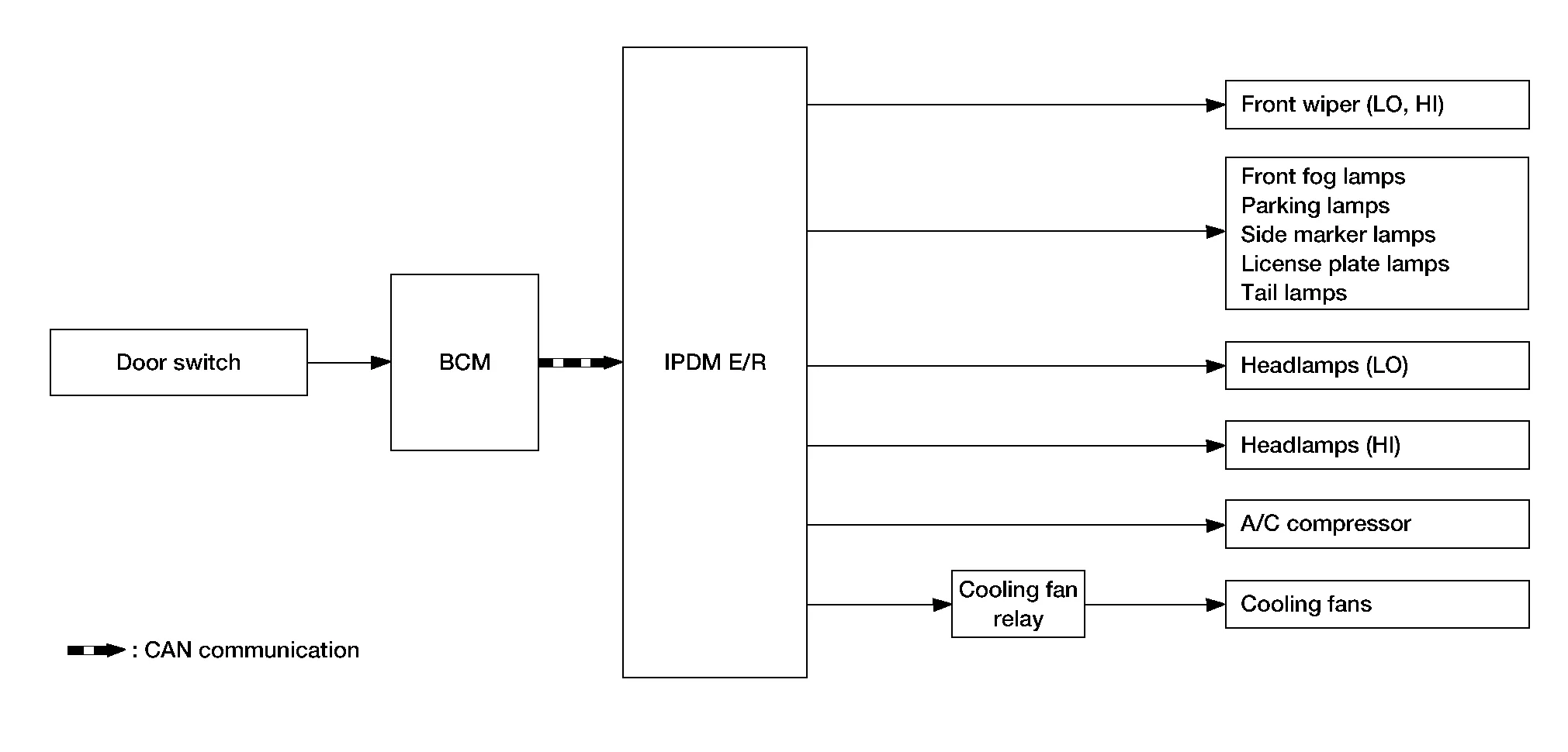
In auto active test mode, the IPDM E/R sends a drive signal to the following systems to check their operation:
-
Front wiper (LO, HI)
-
Front fog lamps
-
Parking lamps
-
Side marker lamps
-
Tail lamps
-
License plate lamps
-
Headlamps (LO, HI)
-
A/C compressor
-
Cooling fans (LO, HI)
Operation Procedure
CAUTION:
Do not start the engine.
 NOTE:
NOTE:
When auto active test is performed with hood opened, sprinkle water on windshield before hand.
NOTE:
-
If auto active test mode cannot be actuated, check door switch system. Refer to Component Function Check.
-
When auto active test mode has to be cancelled halfway through test, place ignition switch OFF.
-
Close the hood and lift the wiper arms from the windshield. (Prevent windshield damage due to wiper operation)
-
Ignition switch OFF.
-
Ignition switch ON, and within 20 seconds, press the front door switch LH 10 times. Then place the ignition switch OFF.
-
Ignition switch ON within 10 seconds. After that the horn sounds once, and the auto active test starts.
-
After a series of the following operations is repeated 3 times, auto active test is completed.
Inspection in Auto Active Test Mode
When auto active test mode is actuated, the following operation sequence is repeated 3 times.
| Operation sequence | Inspection Location | Operation |
|---|---|---|
| 1 | Front wiper | LO for 3 seconds → HI for 3 seconds |
| 2 |
|
10 seconds |
| 3 | Headlamps | LO ⇔ HI 5 times |
| 4 | A/C compressor | ON ⇔ OFF 5 times |
| 5 | Cooling fans | LO for 5 seconds → MID for 3 seconds → HI for 2 seconds |
Concept of auto active test
-
IPDM E/R starts the auto active test with the door switch signals transmitted by BCM via CAN communication. Therefore, the CAN communication line between IPDM E/R and BCM is considered normal if the auto active test starts successfully.
-
The auto active test facilitates troubleshooting if any systems controlled by IPDM E/R cannot be operated.
Diagnosis chart in auto active test mode
| Symptom | Inspection contents | Possible cause | |
|---|---|---|---|
|
Any of the following components do not operate
|
Perform auto active test. Does the applicable system operate? |
YES | BCM signal input circuit |
| NO |
|
||
| Cooling fans do not operate |
Perform auto active test. Do the cooling fans operate? |
YES |
|
| NO |
|
||
CAUTION:
After disconnecting the CONSULT vehicle interface (VI) from the data link connector, the ignition must be cycled OFF → ON (for at least 5 seconds) → OFF. If this step is not performed, the BCM may not go to "sleep mode", potentially causing a discharged battery and a no-start condition.
APPLICATION ITEM
CONSULT performs the following functions via CAN communication with IPDM E/R:
| Direct Diagnostic Mode | Description |
|---|---|
| ECU Identification | The IPDM E/R part number is displayed. |
| Self Diagnostic Result | The IPDM E/R self diagnostic results are displayed. |
| Data Monitor | The IPDM E/R input/output data is displayed in real time. |
| Active Test | The IPDM E/R activates outputs to test components. |
| CAN Diag Support Mntr | The result of transmit/receive diagnosis of CAN communication is displayed. |
ECU IDENTIFICATION
The IPDM E/R part number is displayed.
SELF DIAGNOSTIC RESULT
Refer to DTC Index.
DATA MONITOR
| Monitor Item [Unit] |
Main Signals | Description |
|---|---|---|
| MOTOR FAN REQ [%] | × | Indicates cooling fan speed signal received from ECM on CAN communication line. |
| AC COMP REQ [On/Off] | × | Indicates A/C compressor request signal received from ECM on CAN communication line. |
| TAIL&CLR REQ [On/Off] | × | Indicates position light request signal received from BCM on CAN communication line. |
| HL LO REQ [On/Off] | × | Indicates low beam request signal received from BCM on CAN communication line. |
| HL HI REQ [On/Off] | × | Indicates high beam request signal received from BCM on CAN communication line. |
| FR FOG REQ [On/Off] | × | Indicates front fog light request signal received from BCM on CAN communication line. |
| FR WIP REQ [Stop/1LOW/Low/Hi] | × | Indicates front wiper request signal received from BCM on CAN communication line. |
| WIP AUTO STOP [STOP P/ACT P] | × | Indicates condition of front wiper auto stop signal. |
| WIP PROT [Off/BLOCK] | × | Indicates condition of front wiper fail-safe operation. |
| IGN RLY1 -REQ [On/Off] | Indicates ignition switch ON signal received from BCM on CAN communication line. | |
| IGN RLY [On/Off] | × | Indicates condition of ignition relay. |
| PUSH SW [On/Off] | Indicates condition of push-button ignition switch. | |
| INTER/NP SW [On/Off] | Indicates condition of CVT shift position. | |
| ST RLY CONT [On/Off] | Indicates starter relay status signal received from BCM on CAN communication line. | |
| IHBT RLY -REQ [On/Off] | Indicates starter control relay signal received from BCM on CAN communication line. | |
| ST/INHI RLY [Off/ ST /INHI] | Indicates condition of starter relay and starter control relay. | |
| DETENT SW [On/Off] | Indicates condition of CVT shift selector (park position switch). | |
| DTRL REQ [Off] | Indicates daytime light request signal received from BCM on CAN communication line. | |
| OIL P SW [Open/Close] |
The item is indicated, but not monitored. |
|
| HOOD SW [On/Off] | Indicates condition of hood switch. | |
| THFT HRN REQ [On/Off] | Indicates theft warning horn request signal received from BCM on CAN communication line. | |
| HORN CHIRP [On/Off] | Indicates horn reminder signal received from BCM on CAN communication line. | |
| HOOD SW 2 [On/Off] | Indicates condition of hood switch 2. |
ACTIVE TEST
| Test item | Description |
|---|---|
| HORN | This test is able to check horn operation [On]. |
| FRONT WIPER | This test is able to check wiper motor operation [Hi/Lo/Off]. |
| MOTOR FAN | This test is able to check cooling fan operation [4/3/2/1]. |
| EXTERNAL LAMPS | This test is able to check external lamp operation [Fog/Hi/Lo/TAIL/Off]. |
 Power Consumption Control System
System Description
SYSTEM DIAGRAMINPUT SIGNAL AND OUTPUT SIGNALMajor signal transmission between each unit via communication lines is shown in the following table: Component parts Signal description
IPDM E/R
Each unit transmits the sleep-ready signal (ready) to BCM when all of the CAN sleep conditions are fulfilled...
 Ecu Diagnosis Information. Ipdm E/r
Values on the Diagnosis Tool
NOTE:
The following table includes information (items) inapplicable to this Nissan Murano vehicle. For information (items) applicable to this vehicle, refer to CONSULT display items:
Monitor Item Condition Value/Status
MOTOR FAN REQ
Engine idle speed
Changes depending on engine coolant temperature, air conditioner operation status, Nissan Murano vehicle speed, etc...
Other information:
Nissan Murano (Z52) 2015-2024 Service Manual: Power Consumption Control System
System Description SYSTEM DIAGRAMINPUT SIGNAL AND OUTPUT SIGNALMajor signal transmission between each unit via communication lines is shown in the following table: Component parts Signal description IPDM E/R Each unit transmits the sleep-ready signal (ready) to BCM when all of the CAN sleep conditions are fulfilled...
Nissan Murano (Z52) 2015-2024 Service Manual: Additional Service When Replacing Control Unit
Description AIR BAG DIAGNOSIS SENSOR UNITVehicle specifications are not yet written in a new air bag diagnosis sensor unit. It is therefore necessary to write the specifications to the new unit and then perform “Re/programming, Configuration” with CONSULT...
Categories
- Manuals Home
- Nissan Murano Owners Manual
- Nissan Murano Service Manual
- System malfunction
- Checking engine oil level
- High Beam Assist (if so equipped)
- New on site
- Most important about car
Fuel gauge

The gauge indicates the approximate fuel level in the tank.
The gauge may move slightly during braking, turning, acceleration, or going up or down hills.
The gauge needle returns to 0 (Empty) after the ignition switch is placed in the OFF position.