Nissan Murano: System Description / Diagnosis System (adas Control Unit 2)
APPLICATION ITEMS
CONSULT performs the following functions via CAN communication using ADAS control unit.
| Diagnosis mode | Description |
|---|---|
| Configuration |
|
| Work support | Displays causes of automatic system cancellation occurred during system control |
| Self Diagnostic Result | Displays the name of a malfunctioning system stored in the ADAS control unit |
| Data Monitor | Displays ADAS control unit input/output data in real time |
| Active Test | Enables an operational check of a load by transmitting a driving signal from the ADAS control unit to the load |
| ECU Identification | Displays ADAS control unit part number |
| CAN Diag Support Monitor | Displays a reception/transmission state of CAN communication and ITS communication |
CONFIGURATION
Configuration includes functions as follows.
| Function | Description | |
|---|---|---|
| Read/Write Configuration | Before Replace ECU | Allows the reading of Nissan Murano vehicle specification written in ADAS control unit to store the specification in CONSULT. |
| After Replace ECU | Allows the writing of the Nissan Murano vehicle information stored in CONSULT into the ADAS control unit. | |
| Manual Configuration | Allows the writing of the Nissan Murano vehicle specification into the ADAS control unit by hand. | |
WORK SUPPORT
| Work support items | Description |
|---|---|
| CAUSE OF AUTO-CANCEL 1 |
Displays causes of automatic system cancellation occurred during control of the following systems
|
| CAUSE OF AUTO-CANCEL 4 |
Displays causes of automatic braking system cancellation occurred during control of the following systems
|
 NOTE:
NOTE:
-
Causes of the maximum five cancellations (system cancel) are displayed.
-
The displayed cancellation causes display the number of the ignition switch ON/OFF up to 254. It is fixed to 254 if it is over 254. It returns to 0 when the same cancellation cause is detected again.
Display Items for The Cause of Automatic Cancellation 1
| Cause of cancellation | Nissan Murano Vehicle-to-vehicle distance control mode | Conventional (fixed speed) cruise control mode | Automatic Emergency Braking | Description |
| OPERATING ABS | × | × | ABS function was operated | |
| OPERATING TCS | × | × | TCS function was operated | |
| OPERATING VDC | × | × | × | VDC function was operated |
| ECM CIRCUIT | × | × | ECM did not permit ICC operation | |
| OPE SW VOLT CIRC | × | × | The ICC steering switch input voltage is not within standard range | |
| OP SW DOUBLE TOUCH | × | × | ICC steering switches were pressed at the same time | |
| VHCL SPD DOWN | × | × |
Nissan Murano Vehicle speed lower than the speed as follows
|
|
| WHL SPD ELEC NOISE | × | × | Wheel speed sensor signal caught electromagnetic noise | |
| VDC/TCS OFF SW | × | × | VDC OFF switch was pressed | |
| VHCL SPD UNMATCH | × | × | Wheel speed became different from CVT Nissan Murano vehicle speed | |
| TIRE SLIP | × | × | Wheel slipped | |
| IGN LOW VOLT | × | × | × | Decrease in ADAS control unit ignition voltage |
| PARKING BRAKE ON | × | × | The parking brake is operating | |
| WHEEL SPD UNMATCH | × | × | The wheel speeds of 4 wheels are out of the specified values | |
| INCHING LOST | × | A Nissan Murano vehicle ahead is not detected during the following driving when the vehicle speed is approximately 24 km/h (15 MPH) or less | ||
| CAN COMM ERROR | × | × | × | ADAS control unit received an abnormal signal with CAN communication |
| ABS/TCS/VDC CIRC | × | × | × | An abnormal condition occurs in VDC/TCS/ABS system |
| ECD CIRCUIT | × | × | × | An abnormal condition occurs in ECD system |
| ENG SPEED DOWN | × | × | Engine speed became extremely low while controlling ICC system | |
| ASCD VHCL SPD DTAC | × | Nissan Murano Vehicle speed is detached from set vehicle speed | ||
| ASCD DOUBLE COMD | × | Cancel switch and operation switch are detected simultaneously | ||
| ICC SENSOR CAN COMM ERR | × | × | Communication error between ADAS control unit and the distance sensor (ICC sensor) | |
| ABS WARNING LAMP | × | ABS warning lamp ON | ||
| FR RADAR BLOCKED | × | × | Inclusion of dirt or stains on the distance sensor (ICC sensor) area of the front bumper | |
| FEB) CURVATURE | × | Road curve was more than the specified value | ||
| FEB) YAW RATE | × | Detected yawing speed was more than the specified value | ||
| FEB) LTRL ACCELERATION | × | Detected lateral speed is the specified value or more | ||
| RADAR INTERFERENCE | × | × | Distance sensor (ICC sensor) receives electromagnetic interference | |
| NO RECORD | × | × | — |
Display Items for The Cause of Automatic Cancellation 4
| Cause of cancellation | Description |
| CAN COMM ERROR | ADAS control unit received an abnormal signal with CAN communication |
| VDC OFF SW | VDC OFF switch was pressed |
| ACCEL IS OPERATED 1 | Accelerator pedal was depressed |
| ACCEL IS OPERATED 2 | Accelerator pedal was depressed |
| ECD CIRCUIT | ADAS control unit received and abnormal signal with CAN communication |
| GRADIENT LARGE | Slope, such as uphill, inclination was too steep |
| IGN LOW VOLT | Decrease in ADAS control unit ignition voltage |
| BRAKE IS OPERATED | Brake pedal was operated |
| STEERING ANGLE LARGE | Steering angle was more than the specified value |
| SONAR CIRCUIT | Malfunction of sonar control unit |
| NO RECORD | — |
SELF DIAGNOSTIC RESULT
Refer to DTC Index.
NOTE:
-
The details of time display are as per the following.
-
CRNT: A malfunction is detected now
-
PAST: A malfunction was detected in the past
-
-
IGN counter is displayed on FFD (Freeze Frame Data).
-
0: The malfunctions that are detected now
CAN communication system (U1000, U1010)
-
1 - 39: It increases like 0 → 1 → 2 ··· 38 → 39 after returning to the normal condition whenever the ignition switch OFF → ON. It returns to 0 when a malfunction is detected again in the process.
-
If it is over 39, it is fixed to 39 until the self-diagnosis results are erased.
Other than CAN communication system (Other than U1000, U1010)
-
1 - 49: It increases like 0 → 1 → 2 ··· 38 → 49 after returning to the normal condition whenever the ignition switch OFF → ON. It returns to 0 when a malfunction is detected again in the process.
-
If it is over 49, it is fixed to 49 until the self-diagnosis results are erased.
-
DATA MONITOR
NOTE:
The following table includes information (items) inapplicable to this Nissan Murano vehicle. For information (items) applicable to this vehicle, refer to CONSULT display items.
|
Monitored item [Unit] | ALL SIG (ICC) | MAIN SIG (ICC) | MAIN SIG (LDW/I-LI) | MAIN SIG (BSW/BSI) | Description |
|---|---|---|---|---|---|
|
MAIN SW [On/Off] |
× | × | × | × | Indicates [On/Off] status as judged from ICC steering switch |
|
SET/COAST SW [On/Off] |
× | × | Indicates [On/Off] status as judged from ICC steering switch | ||
|
CANCEL SW [On/Off] |
× | × | Indicates [On/Off] status as judged from ICC steering switch | ||
|
RESUME/ACC SW [On/Off] |
× | × | Indicates [On/Off] status as judged from ICC steering switch | ||
|
DISTANCE SW [On/Off] |
× | Indicates [On/Off] status as judged from ICC steering switch | |||
|
CRUISE OPE [On/Off] |
× | × | Indicates whether controlling or not (ON means “controlling”) | ||
|
BRAKE SW [On/Off] |
× | × | × | × | Indicates [On/Off] status as judged from brake pedal position switch signal (ECM transmits brake switch signal through CAN communication) |
|
STOP LAMP SW [On/Off] |
× | × | × | × | Indicates [On/Off] status as judged from stop lamp switch signal (ECM transmits stop lamp switch signal through CAN communication) |
|
IDLE SW [On/Off] |
× | Indicates [On/Off] status of idle switch read from ADAS control unit through CAN communication (ECM transmits On/Off status through CAN communication) | |||
|
SET DISTANCE [Short/Mid/Long] |
× | × | Indicates set distance memorized in ADAS control unit | ||
|
CRUISE LAMP [On/Off] |
× | × | Indicates [On/Off] status of MAIN switch indicator output | ||
|
OWN VHCL [On/Off] |
× | Indicates [On/Off] status of own Nissan Murano vehicle indicator output | |||
|
VHCL AHEAD [On/Off] |
× | Indicates [On/Off] status of Nissan Murano vehicle ahead detection indicator output | |||
|
ICC WARNING [On/Off] |
× | Indicates [On/Off] status of ICC system warning lamp output | |||
|
VHCL SPEED SE [km/h] or [mph] |
× | × | × | × | Indicates Nissan Murano vehicle speed calculated from ADAS control unit through CAN communication [ABS actuator and electric unit (control unit) transmits Nissan Murano vehicle speed signal (wheel speed) through CAN communication] |
|
SET VHCL SPD [km/h] or [mph] |
× | × | Indicates set Nissan Murano vehicle speed memorized in ADAS control unit | ||
|
BUZZER O/P [On/Off] |
× | Indicates [On/Off] status of ICC warning chime output | |||
|
THRTL SENSOR [deg] |
× | × |
The item is displayed, but it is not used. |
||
|
ENGINE RPM [rpm] |
× | Indicates engine speed read from ADAS control unit through CAN communication (ECM transmits engine speed signal through CAN communication) | |||
|
WIPER SW [OFF/LOW/HIGH] |
× | Indicates wiper [OFF/LOW/HIGH] status (BCM transmits front wiper request signal through CAN communication) | |||
|
BA WARNING [On/Off] |
× | Indicates [On/Off] status of AEB indicator lamp output | |||
|
STP LMP DRIVE [On/Off] |
× | × | Indicates [On/Off] status of brake hold drive signal | ||
|
D RANGE SW [On/Off] |
× | Indicates [On/Off] status of “D” or “M” positions read from ADAS control unit through CAN communication; ON when position “D” or “M” (TCM transmits shift position signal through CAN communication). | |||
|
NP SW SIG [On/Off] |
× | × | Indicates [On/Off] status as judged from park/neutral position switch signal (ECM transmits park/neutral position switch signal through CAN communication) | ||
|
SL MAIN SW [On/Off] |
× | × | Indicates [On/Off] status as judged from steering switch | ||
|
PKB SW [On/Off] |
× | Parking brake switch status [On/Off] judged from the parking brake switch signal that ADAS control unit readout via CAN communication is displayed (combination meter transmits the parking brake switch signal via CAN communication) | |||
|
PWR SUP MONI [V] |
× | × | Indicates IGN voltage input by ADAS control unit | ||
|
THRTL OPENING [%] |
× | x | x | Indicates throttle position read from ADAS control unit through CAN communication (ECM transmits accelerator pedal position signal through CAN communication). | |
|
GEAR [1, 2, 3, 4, 5, 6, 7] |
× | x | Indicates CVT gear position read from ADAS control unit through CAN communication (TCM transmits current gear position signal through CAN communication) | ||
|
MODE SIG [OFF, ICC, ASCD] |
× | Indicates the active mode from ICC or ASCD [conventional (fixed speed) cruise control mode] | |||
|
SET DISP IND [On/Off] |
× | Indicates [On/Off] status of SET switch indicator output | |||
|
DYNA ASIST SW [On/Off] |
× | × | Indicates [On/Off] status as judged from ICC steering switch signal (ECM transmits ICC steering switch signal through CAN communication) | ||
|
LDW SYSTEM ON [On/Off] |
× | Indicates [On/Off] status of LDW system | |||
|
LDW ON INDICATOR [On/Off] |
Indicates [On/Off] status of LDW system display output | ||||
|
LDP ON IND [On/Off] |
× | Indicates [On/Off] status of I-LI system display output | |||
|
LDP SYSTEM ON [On/Off] |
× | Indicates [On/Off] status of I-LI system | |||
|
LANE DPRT W/L [On/Off] |
x | × | Indicates [On/Off] status of LDWI-LI warning display (Yellow) output | ||
|
STATUS signal [Stnby/Warn/Cancl/Off] |
× | Indicates a control state of I-LI system | |||
|
CAMERA LOST [Detect/Deviate/Both] |
x | × |
Indicates a lane marker detection state judged from a lane marker detection signal read by the ADAS control unit via ITS communication (Lane camera unit transmits a lane marker signal via ITS communication) |
||
|
SIDE G [G] |
x | × | × |
Indicates lateral G acting on the Nissan Murano vehicle. This lateral G is judged from a side G sensor signal read by ADAS control unit via CAN communication (The ABS actuator and electric unit (control unit) transmits a side G sensor signal via CAN communication) |
|
|
ITS SETTING ITEM(LDP) [On/Off] |
x | × | × | Indicates the presence or absence of I-LI system. | |
|
ITS SETTING ITEM(BSW) [On/Off] |
x | × | Indicates the presence or absence of BSW system. | ||
|
Turn signal [OFF/LH/RH/LH&RH] |
× | × | Indicates turn signal operation status read from ADAS control unit through CAN communication (BCM transmits turn indicator signal through CAN communication) | ||
|
LDP SELECT [On/Off] |
× | × | × | × | Indicates an ON/OFF state of I-LI system. I-LI system can be set to ON/OFF by selecting “Driving Aids”⇒“Lane” in the combination meter |
|
LDW SELECT [On/Off] |
× | × | × | × | Indicates an ON/OFF state of the LDW system. The LDW system can be set to ON/OFF by selecting “Driving Aids”⇒“Lane” of the integral switch |
|
BSW SELECT [On/Off] |
× | × | × | × | Indicates an ON/OFF state of the BSW system. The BSW system can be set to ON/OFF by selecting “Driving Aids”⇒“Blind spot” of the integral switch |
|
BSW SYSTEM ON [On/Off] |
× | × | Indicates [On/Off] status of BSW system | ||
|
BSW/BSI WARN LMP [On/Off] |
× | Indicates [On/Off] status of Blind Spot warning malfunction | |||
|
BATTERY CIRCUIT OFF [On/Off] |
The item is displayed, but it is not used |
||||
|
LDP WARNING INDICATOR [On/Off] |
× | Indicates [On/Off] status of I-LI warning display (Yellow) output | |||
|
LDW ON INDICATOR [On/Off] |
× | Indicates [On/Off] status of LDW system ON display output | |||
|
LDW WARNING INDICATOR [On/Off] |
× | Indicates [On/Off] status of LDW system warning display output | |||
|
ITS SETTING ITEM(LDP) [On/Off] |
× | × | × | × | Indicates the presence or absence of I-LI system. |
| ITS SETTING ITEM (BSI) | × | × | × | × | Indicates the presence or absence of Blind Spot Intervention system. |
|
BSW ON INDICATOR [On/Off] |
× | Indicates [On/Off] status of BSW system ON display output | |||
|
FUNC ITEM(FEB) [On/Off] |
Indicates systems which can be set to ON/OFF by selecting “Driver Assistance”⇒“Emergency Brake” of the combination meter | ||||
|
FEB SELECT [On/Off] |
Indicates an ON/OFF state of the AEB system. The AEB system can be set to ON/OFF by selecting “Driver Assistance”⇒“Emergency Brake” of the combination meter | ||||
|
FEB SW [On/Off] |
The item is displayed, but it is not used |
||||
|
FEB SW OPE [On/Off] |
× |
The item is displayed, but it is not used |
|||
|
FEB SW IND [On/Off] |
× |
The item is displayed, but it is not used |
|||
|
RAB warning lamp (operation) [on/off] |
Indicates [On/Off] status of RAB system warning indicator. | ||||
|
RAB warning lamp (malf) [on/off] |
Indicates [On/Off] status of RAB system warning light. |
ACTIVE TEST
CAUTION:
-
Never perform “Active Test” while driving the vehicle.
-
The “Active Test” cannot be performed when the following systems malfunction is displayed.
-
ICC system
-
LDW
-
I-LI
-
Blind Spot Warning
-
-
The “Active Test” cannot be performed when the AEB warning lamp is illuminated.
-
Shift the selector lever to “P” position, and then perform the test.
| Test item | Description |
|---|---|
| STOP LAMP | The brake hold drive signal can be operated by ON/OFF operations as necessary, and the stop lamp can be illuminated |
| ICC BUZZER |
Sounds a buzzer used for following systems by arbitrarily operating ON/OFF
|
| BRAKE ACTUATOR | Activates the brake by an arbitrary operation |
| LDP BUZZER |
Sounds a buzzer used for following systems by arbitrarily operating ON/OFF
|
| LDP ON IND | The I-LI system display can be illuminated by ON/OFF operations as necessary |
| LANE DEPARTURE W/L | The LDW/I-LI warning can be illuminated by ON/OFF operations as necessary |
| BSW WARNING LAMP | The Blind Spot Warning system display can be illuminated by ON/OFF operations as necessary |
| BSW ON INDICATOR | The Blind Spot Warning system display can be illuminated by ON/OFF operations as necessary |
| LDW ON INDICATOR | The LDW system display can be illuminated by ON/OFF operations as necessary |
| LDP WARNING INDICATOR | The I-LI malfunction can be illuminated by ON/OFF operations as necessary |
| LDW WARNING INDICATOR | The LDW malfunction can be illuminated by ON/OFF operations as necessary |
| Vibration motor | The steering vibration motor can be operated ON/OFF |
| RAB warning lamp (operation) | The RAB system display can be illuminated by ON/OFF operations as necessary |
| RAB warning lamp (malfunction) | The RAB malfunction can be illuminated by ON/OFF operations as necessary |
| ADAS buzzer 2 |
Sounds a buzzer used for following systems by arbitrarily operating ON/OFF
|
STOP LAMP
| Test item | Operation | Description | Stop lamp |
|---|---|---|---|
| STOP LAMP | Off | Stops transmitting the brake hold drive signal to end the test | OFF |
| On | Transmits the brake hold drive signal | ON |
ICC BUZZER
| Test item | Operation | Description | Operation sound |
|---|---|---|---|
| ICC BUZZER | MODE1 | Transmits the buzzer output signals to the ADAS control unit via ITS communication | Intermittent beep sound |
| Test start | Starts the tests of “MODE1” | — | |
| Reset | Stops transmitting the buzzer output signal to end the test | — | |
| End | Returns to the “SELECT TEST ITEM” screen | — |
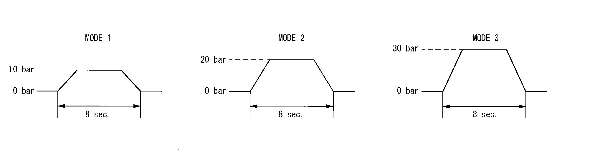
BRAKE ACTUATOR
NOTE:
The test can be performed only when the engine is running.
| Test item | Operation | Description | “PRESS SENS” value |
|---|---|---|---|
| BRAKE ACTUATOR | MODE1 | Transmits the brake fluid pressure control signal to the ABS actuator and electric unit (control unit) via CAN communication | 10 bar |
| MODE2 | 20 bar | ||
| MODE3 | 30 bar | ||
| Test start | Starts the tests of “MODE1”, “MODE2” and “MODE3” | — | |
| Reset | Stops transmitting the brake fluid pressure control signal to end the test | — | |
| End | Returns to the “SELECT TEST ITEM” screen | — |
NOTE:
The test is finished in 10 seconds after starting
LDP BUZZER
| Test item | Operation | Description | Warning buzzer |
|---|---|---|---|
| LDP BUZZER | Off | Stops transmitting the warning buzzer signal to end the test | — |
| On | Transmits the warning buzzer signal to the warning system buzzer | ON |
LDP ON IND
| Test item | Operation | Description | I-LI system display (Green) |
|---|---|---|---|
| LDP ON IND | Off | Stops transmitting the meter display signal to end the test | — |
| On | Transmits the meter display signal to the combination meter via CAN communication | ON |
LANE DEPARTURE W/L
| Test item | Operation | Description | Lane departure system display (Yellow) |
|---|---|---|---|
| LANE DEPARTURE W/L | Off | Stops transmitting the meter display signal to end the test | — |
| On | Transmits the meter display signal to the combination meter via CAN communication | ON |
BSW ON LAMP
| Test item | Operation | Description | Lane departure system display (Yellow) |
|---|---|---|---|
| BSW ON INDICATOR | Off | Stops transmitting the meter display signal below to end the test | — |
| On | Transmits the meter display signal to the combination meter via CAN communication | ON |
LDW ON INDICATOR
| Test item | Operation | Description | LDW system display (White) |
|---|---|---|---|
| LDW ON INDICATOR | Off | Stops transmitting the meter display signal to end the test | — |
| On | Transmits the meter display signal to the combination meter via CAN communication | ON |
LDP WARNING INDICATOR
| Test item | Operation | Description | I-LI malfunction (Yellow) |
|---|---|---|---|
| LDP WARNING INDICATOR | Off | Stops transmitting the meter display signal to end the test | — |
| On | Transmits the meter display signal to the combination meter via CAN communication | ON |
LDW WARNING INDICATOR
| Test item | Operation | Description | LDW malfunction (Yellow) |
|---|---|---|---|
| LDW WARNING INDICATOR | Off | Stops transmitting the meter display signal to end the test | — |
| On | Transmits the meter display signal to the combination meter via CAN communication | ON |
VIBRATION MOTOR
| Test item | Operation | Description | Vibration motor |
|---|---|---|---|
| Vibration motor | Off | Stops sending the steering vibration motor signal to end the test | OFF |
| On | Transmits the steering vibration motor signal | ON |
RAB WARNING LAMP (OPERATION)
| Test item | Operation | Description | RAB system warning light |
|---|---|---|---|
| RAB warning lamp (operation) | Off | Stops transmitting the meter display signal below to end the test | — |
| On | Transmits the meter display signal to the combination meter via CAN communication | ON |
RAB WARNING LAMP (MALFUNCTION)
| Test item | Operation | Description | RAB system warning indicator |
|---|---|---|---|
| RAB warning lamp (malfunction) | Off | Stops transmitting the meter display signal below to end the test | — |
| On | Transmits the meter display signal to the combination meter via CAN communication | ON |
ADAS BUZZER 2
| Test item | Operation | Description | Warning buzzer |
|---|---|---|---|
| ADAS buzzer 2 | Off | Stops transmitting the warning buzzer signal to end the test | — |
| On | Transmits the warning buzzer signal to the warning system buzzer | ON |
ECU IDENTIFICATION
Displays ADAS control unit parts number.
 System
System Description
SYSTEM DIAGRAMADAS CONTROL UNIT INPUT/OUTPUT SIGNAL ITEMInput Signal Item Transmit unit Signal name Description
ECM
CAN communication
Closed throttle position signal
Receives idle position state (ON/OFF)
Accelerator pedal position signal
Receives accelerator pedal position (angle)
ICC prohibition signal
Receives an operable/inoperable state of the ICC system
Snow mode switch signal
Receives an operational state of the snow mode
Steering switch signal
Main switch signal
Receives the operational state of the ICC steering switch
SET/COAST switch signal
CANCEL switch signal
RESUME/ACCELERATE switch signal
DISTANCE switch signal
Engine speed signal
Receives engine speed
Stop lamp switch signal
Receives an operational state of the brake pedal
Brake pedal position switch signal
Receives an operational state of the brake pedal
TCM
CAN communication
Input speed signal
Receives the number of revolutions of input shaft
Current gear position signal
Receives a current gear position
Shift position signal
Receives a selector lever position
Output shaft revolution signal
Receives the number of revolutions of output shaft
ABS actuator and electric unit (control unit)
CAN communication
ABS malfunction signal
Receives a malfunction state of ABS
ABS operation signal
Receives an operational state of ABS
ABS warning lamp signal
Receives an ON/OFF state of ABS warning lamp
TCS malfunction signal
Receives a malfunction state of TCS
TCS operation signal
Receives an operational state of TCS
VDC OFF switch signal
Receives an ON/OFF state of VDC
VDC malfunction signal
Receives a malfunction state of VDC
VDC operation signal
Receives an operational state of VDC
Nissan Murano Vehicle speed signal (ABS)
Receives wheel speeds of four wheels
Stop lamp switch signal
Receives an operational state of the brake pedal
Yaw rate signal
Receives yaw rate acting on the Nissan Murano vehicle
Side G sensor signal
Receives lateral G acting on the Nissan Murano vehicle
BCM
CAN communication
Front wiper request signal
Receives an operational state of front wiper(s)
Turn indicator signal
Receives an operational state of the turn signal lamp and the hazard lamp
Tail lamp request signal
Receives a tail lamp request signal
Brake pedal position switch signal
Receives a brake pedal position switch signal
Stop lamp switch signal
Receives a stop lamp switch signal
Stop lamp status signal
Receives a stop lamp status signal
Dimmer signal
Receives ON/OFF state of dimmer signal
Steering angle sensor
CAN communication
Steering angle sensor malfunction signal
Receives a malfunction state of steering angle sensor
Steering angle sensor signal
Receives the number of revolutions, turning direction of the steering wheel
Steering angle speed signal
Receives the turning angle speed of the steering wheel
Detected lane condition signal
Receives detection results of lane marker
Combination meter
CAN communication
System selection signal
Receives a selection state of each item in “Driver Assistance” selected with the Nissan Murano vehicle information display
Parking brake switch signal
Receives an operational state of the parking brake
Distance sensor (ICC sensor)
ITS communication
ICC sensor signal
Receives detection results, such as the presence or absence of a Nissan Murano vehicle ahead and distance from the vehicle
Lane camera unit
(if equipped)
ITS communication
Detected lane condition signal
Receives detection results of lane marker
Detected pedestrian condition signal
Receives detection results of pedestrian
Side radar LH, RH
ITS communication
Nissan Murano Vehicle detection signal
Receives vehicle detection condition of detection zone
Lane intervention switch
Lane intervention switch signal
Receives an ON/OFF state of the lane intervention switch
Output Signal Item Reception unit Signal name Description
ECM
CAN communication
ICC operation signal
Transmits an ICC operation signal necessary for intelligent cruise control
ABS actuator and electric unit (control unit)
CAN communication
Brake fluid pressure control signal
Transmits a brake fluid pressure control signal to activate the brake
Combination meter
CAN communication
Meter display signal
Handle support indicator signal
Transmits a signal to display a state of the system on the information display
Nissan Murano Vehicle ahead detection indicator signal
Vehicle ahead detection indicator signal
Set Nissan Murano vehicle speed indicator signal
Set distance indicator signal
SET switch indicator signal
MAIN switch indicator signal
Blind Spot Warning warning lamp signal
Transmits a Blind Spot Warning warning lamp signal to turn ON the Blind Spot Warning warning lamp
Intelligent Lane Intervention ON indicator lamp signal
Transmits an Intelligent Lane Intervention ON indicator lamp signal to turn ON the Intelligent Lane Intervention ON indicator lamp
Lane departure warning lamp signal
Transmits a lane departure warning lamp signal to turn ON the lane departure warning lamp
ICC warning lamp signal
Transmits an ICC warning lamp signal to turn ON the ICC system warning lamp
AEB indicator lamp signal
Transmits a signal to turn ON the AEB indicator
Transmits a signal to turn OFF the AEB indicator
Distance sensor (ICC sensor)
ITS communication
Nissan Murano Vehicle speed signal
Transmits vehicle speed calculated by the ADAS control unit
Steering angle sensor signal
Transmits steering angle sensor signal received from the steering angle sensor
Side radar LH, RH
ITS communication
Nissan Murano Vehicle speed signal
Transmits vehicle speed calculated by the ADAS control unit
Blind Spot Warning indicator signal
Transmits a Blind Spot Warning indicator signal to turn ON the Blind Spot Warning indicator
Blind Spot Warning indicator dimmer signal
Transmits a Blind Spot Warning indicator dimmer signal to dim Blind Spot Warning indicator
Steering angle sensor
CAN communication
ICC brake hold drive signal
Activates brake hold and turns ON the stop lamp
BCM
CAN communication
Stop lamp ON request signal
Transmits a stop lamp ON request signal
Intelligent Lane Intervention system ON indicator
Intelligent Lane Intervention system ON indicator signal
Turns ON the Intelligent Lane Intervention system ON indicator
Warning system buzzer
Warning buzzer signal
Activates warning system buzzer
DESCRIPTION
ADAS* control unit controls the following systems based on ITS communication signal and CAN communication signal from each control unit...
 Ecu Diagnosis Information. Adas Control Unit 2
Values on the Diagnosis Tool
NOTE:
The following table includes information (items) inapplicable to this Nissan Murano vehicle. For information (items) applicable to this vehicle, refer to CONSULT display items...
Other information:
Nissan Murano (Z52) 2015-2024 Owners Manual: System maintenance
The lane camera unit for the LDW system is located above the inside mirror. To keep the proper operation of the LDW system and prevent a system malfunction, be sure to observe the following: Always keep the windshield clean. Do not attach a sticker (including transparent material) or install an accessory near the camera unit...
Nissan Murano (Z52) 2015-2024 Service Manual: Rear Lh
Diagnosis Procedure PERFORM INITIALIZATION PROCEDURE Initialization procedure is performed and operation is confirmed. Refer to Work Procedure . Is the inspection result normal? YES>> Inspection End. NO>> GO TO 2. CONFIRM THE OPERATION Confirm the operation again...
Categories
- Manuals Home
- Nissan Murano Owners Manual
- Nissan Murano Service Manual
- Warning lights
- Passenger compartment
- Turning the AEB system on/off
- New on site
- Most important about car
Seatback pockets

Theremaybe one or two seatback pockets located on the back of the driver and passenger seats. The pockets can be used to store maps.
WARNING