Nissan Murano: Driver Assistance System :: Adas Control Unit / Ecu Diagnosis Information. Adas Control Unit 2
 NOTE:
NOTE:
The following table includes information (items) inapplicable to this Nissan Murano vehicle. For information (items) applicable to this vehicle, refer to CONSULT display items.
| Monitor item | Condition | Value/Status | |
|---|---|---|---|
| MAIN SW | Ignition switch ON | When MAIN switch is pressed | On |
| When MAIN switch is not pressed | Off | ||
| SET/COAST SW | Ignition switch ON | When SET/COAST switch is pressed | On |
| When SET/COAST switch is not pressed | Off | ||
| CANCEL SW | Ignition switch ON | When CANCEL switch is pressed | On |
| When CANCEL switch is not pressed | Off | ||
| RESUME/ACC SW | Ignition switch ON | When RESUME/ACCELERATE switch is pressed | On |
| When RESUME/ACCELERATE switch is not pressed | Off | ||
| DISTANCE SW | Ignition switch ON | When DISTANCE switch is pressed | On |
| When DISTANCE switch is not pressed | Off | ||
| CRUISE OPE | Drive the Nissan Murano vehicle and activate the vehicle-to-vehicle distance control mode | When ICC system is controlling | On |
| When ICC system is not controlling | Off | ||
| BRAKE SW | Ignition switch ON | When brake pedal is depressed | Off |
| When brake pedal is not depressed | On | ||
| STOP LAMP SW | Ignition switch ON | When brake pedal is depressed | On |
| When brake pedal is not depressed | Off | ||
| IDLE SW | Engine running | Idling | On |
| Except idling (depress accelerator pedal) | Off | ||
| VHCL SPEED SE | While driving | Displays the Nissan Murano vehicle speed calculated by ADAS control unit | |
| ENGINE RPM | Engine running | Equivalent to tachometer reading | |
| THRTL SENSOR |
The item is displayed, but it is not used. |
0.0 | |
| BA WARNING | Engine running |
AEB OFF indicator lamp ON
|
On |
|
AEB OFF indicator lamp OFF
|
Off | ||
| STP LMP DRIVE | Drive the Nissan Murano vehicle and activate the vehicle-to-vehicle distance control mode | When ICC brake hold drive is activated | On |
| When ICC brake hold drive is not activated | Off | ||
| D RANGE SW | Engine running | When the shift selector is in “D” position or manual mode | On |
| When the shift selector is in any position other than “D” or manual mode | Off | ||
| NP RANGE SW | Engine running | When the shift selector is in “N”, “P” position | On |
| When the shift selector is in any position other than “N”, “P” | Off | ||
| PKB SW | Ignition switch ON | When the parking brake is applied | On |
| When the parking brake is released | Off | ||
| PWR SUP MONI | Engine running | Power supply voltage value of ADAS control unit | |
| VHCL SPD AT | While driving | Value of CVT Nissan Murano vehicle speed sensor signal | |
| THRTL OPENING | Engine running | Depress accelerator pedal | Displays the throttle position |
| GEAR | While driving | Displays the gear position | |
| MODE SIG | Start the engine and press MAIN switch | When ICC system is deactivated | Off |
| When Nissan Murano vehicle-to-vehicle distance control mode is activated | ICC | ||
| When conventional (fixed speed) cruise control mode is activated | ASCD | ||
| SET DISP IND |
|
SET Nissan Murano vehicle speed indicator ON | On |
| SET Nissan Murano vehicle speed indicator OFF | Off | ||
| DISTANCE | Drive the Nissan Murano vehicle and activate the vehicle-to-vehicle distance control mode | When a Nissan Murano vehicle ahead is detected | Displays the distance from the preceding Nissan Murano vehicle |
| When a vehicle ahead is not detected | 0.0 | ||
| RELATIVE SPD | Drive the Nissan Murano vehicle and activate the vehicle-to-vehicle distance control mode | When a Nissan Murano vehicle ahead is detected | Displays the relative speed. |
| When a Nissan Murano vehicle ahead is not detected | 0.0 | ||
| DYNA ASIST SW | Ignition switch ON | When dynamic driver assistance switch is pressed | On |
| When dynamic driver assistance switch is not pressed | Off | ||
| LDW SYSTEM ON | Ignition switch ON | When the LDW system is ON | On |
| When the LDW system is OFF | Off | ||
| LDW ON LAMP | Ignition switch ON | When the LDW system is ON | On |
| When the LDW system is OFF | Off | ||
| LANE DPRT W/L | Drive the Nissan Murano vehicle and activate the LDW system or I–LI system | Lane departure warning lamp ON | On |
| Lane departure warning lamp OFF | Off | ||
| LDW BUZER OUTPUT | Drive the Nissan Murano vehicle and activate the LDW/I–LI system or Blind Spot Warning system |
When the buzzer of the following system operates
|
On |
|
When the buzzer of the following system does not operate
|
Off | ||
| WARN REQ | Drive the Nissan Murano vehicle and activate the I–LI system | Lane departure warning is operating | On |
| Lane departure warning is not operating | Off | ||
| Camera lost | Drive the Nissan Murano vehicle and activate the LDW system or I–LI system | Both side lane markers are detected | Detect |
| Deviate side lane marker is lost | Deviate | ||
| Both side lane markers are lost | Both | ||
| Lane unclear | While driving | Lane marker is unclear | On |
| Lane marker is clear | Off | ||
| STATUS signal | Drive the Nissan Murano vehicle and activate the I–LI system | When the I–LI system is ON | Stnby |
| When the I–LI system is operating | Warn | ||
| When the I–LI system is canceled | Cancl | ||
| When the I–LI system is OFF | Off | ||
| Shift position |
|
Displays the shift position | |
| Turn signal | Turn signal lamps OFF | Off | |
| Turn signal lamp LH blinking | LH | ||
| Turn signal lamp RH blinking | RH | ||
| Turn signal lamp LH and RH blinking | LH&RH | ||
| SIDE G | While driving | Nissan Murano Vehicle turning right | Negative value |
| Nissan Murano Vehicle turning left | Positive value | ||
| FUNC ITEM (FCW) | Engine running | On | |
| FUNC ITEM (LDW) | Engine running | On | |
| FUNC ITEM (BSW) | Engine running | On | |
| LDP SELECT | Ignition switch ON | “Intelligent Lane Intervention” set with the integral switch is ON | On |
| “Intelligent Lane Intervention” set with the integral switch is OFF | Off | ||
| FCW SELECT | Ignition switch ON | “Automatic Emergency Braking” set with the integral switch is ON | On |
| “Automatic Emergency Braking” set with the integral switch is OFF | Off | ||
| LDW SELECT | Ignition switch ON | “Lane Departure Warning” set with the integral switch is ON | On |
| “Lane Departure Warning” set with the integral switch is OFF | Off | ||
| BSW SELECT | Ignition switch ON | “Blind Spot Warning” set with the integral switch is ON | On |
| “Blind Spot Warning” set with the integral switch is OFF | Off | ||
| BSW/BSI WARN LMP | Engine running | When the BSW system is malfunctioning | On |
| When the BSW system is normal | Off | ||
| BSW SYSTEM ON | Ignition switch ON | When the BSW system is ON | On |
| When the BSW system is OFF | Off | ||
| FCW SYSTEM ON | Engine running | When the AEB system is ON | On |
| When the AEB system is OFF | Off | ||
| BATTERY CIRCUIT OFF |
The item is displayed, but it is not used. |
Off | |
| LDP WARNING INDICATOR | Engine running | When the I-LI system is malfunctioning | On |
| When the I-LI system is normal | Off | ||
| LDW ON INDICATOR | Engine running | LDW system display ON | On |
| LDW system display OFF | Off | ||
| LDW WARNING INDICATOR | Engine running | When the LDW system is malfunctioning | On |
| When the LDW system is normal | Off | ||
| SYSTEM CANCEL MESSAGE | Engine running | When the Nissan Murano vehicle is normal | NOREQ |
| When the wheel is slipping | SLIP | ||
| When the VDC is OFF | VDC OFF | ||
| CAMERA HI TEMP MSG | Engine running | Lane camera unit high temperature warning display ON | On |
| Lane camera unit high temperature warning display OFF | Off | ||
| ITS SETTING ITEM(LDP) | Ignition switch ON | On | |
| BSW ON INDICATOR | Engine running | BSW system display ON | On |
| BSW system display OFF | Off | ||
| SIDE RADAR BLOCK COND | Engine running | Front bumper or side radar is dirty | On |
| Front bumper and side radar is clean | Off | ||
| LDW WARNING ALERT TIMING | Ignition switch ON | LDW system OFF | Nothing |
| Lane departure warning timing is early setting | Early | ||
| Lane departure warning timing is late setting | Late | ||
| BSW IND BRIGHTNESS | Ignition switch ON | BSW system OFF | Nothing |
| Blind Spot Warning indicator brightness bright | Bright | ||
| Blind Spot Warning indicator brightness normal | Normal | ||
| Blind Spot Warning indicator brightness dark | Dark | ||
| FEB SELECT | Power switch ON | AEB set with the combination meter is ON | On |
| AEB set with the combination meter is OFF | Off | ||
| FEB SW | Set the Nissan Murano vehicle to READY | AEB system ON | On |
| AEB system OFF | Off | ||
| FEB SW OPE |
The item is displayed, but it is not used. |
Off | |
| FEB SW IND |
The item is displayed, but it is not used. |
Off | |
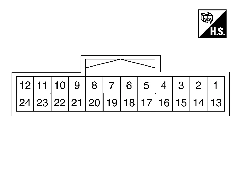
TERMINAL LAYOUT
PHYSICAL VALUES
|
Terminal No. (Wire color) | Description | Condition |
Value (Approx.) | |||
|---|---|---|---|---|---|---|
| + | − | Signal name | Input/Output | |||
|
1 (V) |
Ground | Warning system buzzer drive signal | Output | Ignition switch ON | Warning system buzzer not operating | 0 V |
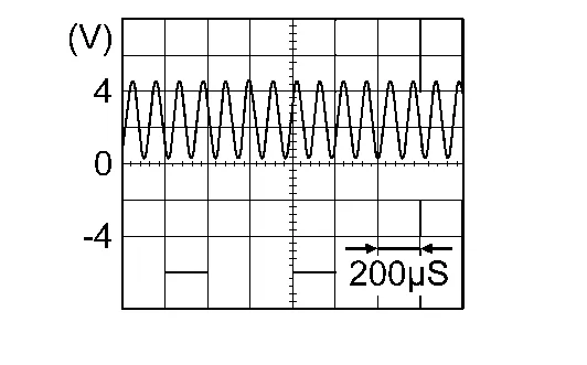
| Warning system buzzer operating |
|
|||||
|
2 (B) |
Ground | — | Ignition switch ON | 0 V | ||
|
3 (Y) |
ITS communication low | — | — | — | — | |
|
4 (L) |
ICC brake hold relay drive signal | Output | Ignition switch ON | — | Battery voltage | |
| AT "STOP LAMP" test of "Active Test" | 0 V | |||||
|
6 (Y) |
ITS communication low | — | — | — | — | |
|
7 (BR) |
Lane intervention switch indicator output | Output | — | — | — | |
|
9 (L) |
CAN high | — | — | — | — | |
|
12 (L) |
Steering vibration motor signal | Output | Ignition switch ON | Operating the steering vibration motor | Battery voltage | |
| Not operating the steering vibration motor | 0 V | |||||
|
13 (LG) |
Driver assistance buzzer drive signal ground | Input | Ignition switch ON | 0 V | ||
|
15 (L) |
ITS communication high | — | — | — | — | |
|
16 (LG) |
Ignition power supply | Input | Ignition switch ON | Battery voltage | ||
|
18 (L) |
ITS communication high | — | — | — | — | |
|
19 (Y) |
CAN low | — | — | — | — | |
|
20 (L) |
CAN high | — | — | — | — | |
|
21 (P) |
CAN low | — | — | — | — | |
|
23 (LG) |
Lane intervention switch | Input | Ignition switch ON | When lane intervention switch is not pressed | Battery voltage | |
| When lane intervention switch is pressed | 0 V | |||||
|
24 (SB) |
Steering vibration motor signal ground | Input | Ignition switch ON | Operating the steering vibration motor | 4 V | |
| Not operating the steering vibration motor | 0 V | |||||
Refer to Fail-safe (ADAS Control Unit).
If multiple DTCs are detected simultaneously, check them one by one depending on the following DTC inspection priority chart.
| Priority | Detected items (DTC) | |
|---|---|---|
| 1 |
|
|
| 2 |
|
|
| 3 |
|
|
| 4 |
|
|
| 5 |
|
|
| 6 |
|
|
| 7 |
|
|
| DTC | CONSULT display | Reference | |
|---|---|---|---|
| C1A00 | 44 | CONTROL UNIT | Refer to DTC Description. |
| 45 | Refer to DTC Description. | ||
| 46 | Refer to DTC Description. | ||
| 48 | Refer to DTC Description. | ||
| 49 | Refer to DTC Description. | ||
| C1A01 | A2 | POWER SUPPLY CIR | Refer to DTC Description. |
| C1A02 | A3 | POWER SUPPLY CIR 2 | Refer to DTC Description. |
| C1A03 | 29 | VHCL SPEED SE CIRC | Refer to DTC Description. |
| 64 | Refer to DTC Description | ||
| C1A04 | 97 | ABS/TCS/VDC CIRC | Refer to DTC Description. |
| C1A05 | 64 | BRAKE SW/STOP L SW | Refer to DTC Description. |
| C1A07 | 97 | CVT CIRCUIT | Refer to DTC Description. |
| C1A0E | 49 | CONTROL UNIT | Refer to DTC Description. |
| C1A13 | 23 | STOP LAMP RLY FIX | Refer to DTC Description. |
| 24 | Refer to DTC Description. | ||
| C1A14 | 62 | ECM CIRCUIT | Refer to DTC Description. |
| 64 | Refer to DTC Description. | ||
| 97 | Refer to DTC Description. | ||
| C1A15 | 64 | GEAR POSITION | Refer to DTC Description. |
| C1A17 | 49 | ICC SENSOR | Refer to DTC Description. |
| C1A1B | 14 | CONTROL UNIT | Refer to DTC Description. |
| C1A1C | 14 | Refer to DTC Description. | |
| C1A1D | 14 | Refer to DTC Description. | |
| C1A1E | 14 | Refer to DTC Description. | |
| C1A1F | 14 | Refer to DTC Description. | |
| C1A24 | 97 | NP RANGE | Refer to DTC Description. |
| C1A26 | 97 | ECD MODE MALF | Refer to DTC Description. |
| C1A27 | 97 | ECD PWR SUPLY CIR | Refer to DTC Description. |
| C1A33 | 97 | CAN TRANSMISSION ERR | Refer to DTC Description. |
| C1A34 | 64 | COMMAND ERROR | Refer to DTC Description. |
| C1A39 | 97 | STRG SEN CIR | Refer to DTC Description. |
| C1A40 | 23 | SYSTEM SWITCH CIRCUIT | Refer to DTC Description. |
| C1A41 | 49 | CONTROL UNIT | Refer to DTC Description. |
| C1A42 | 23 | OPERATION SW CIRC | Refer to DTC Description. |
| C1A42 | 62 | OPERATION SW CIRC | Refer to DTC Description. |
| C1A43 | 23 | OPERATION SW CIRC | Refer to DTC Description. |
| C1A4A | 82 | TCM CAN CIRCUIT1 | Refer to DTC Description. |
| C1B00 | 97 | CAMERA UNIT MALF | Refer to DTC Description. |
| C1B01 | 55 | CAM AIMING INCMP | Refer to DTC Description. |
| C1B03 | 4B | CAN ABNRML TMP DETCT | Refer to DTC Description. |
| C1B53 | 97 | SIDE RDR R MALF | Refer to DTC Description. |
| C1B54 | 97 | SIDE RDR L MALF | Refer to DTC Description. |
| C1B56 | 97 | SONAR CIRCUIT | Refer to DTC Description. |
| C1B5A | 29 | G SENSOR MALF | Refer to DTC Description. |
| C1B5D | 97 | FEB OPE COUNT LIMIT | Refer to DTC Decription. |
| C1B82 | 97 | DIST SEN OFF-CENTER | Refer to DTC Description. |
| C1B84 | 97 | DIST SEN MALFUNCTION | Refer to DTC Description. |
| C1B85 | 4B | DIST SEN ABNORMAL TEMP | Refer to DTC Description. |
| C1B86 | A2 | DIST SEN PWR SUP CIR | Refer to DTC Description. |
| C1B88 | 13 | MOTOR CIRCUIT | Refer to DTC Description. |
| C1B89 | 23 | SPEAKER CIRCUIT | Refer to DTC Description. |
| U0121 | 83 | VDC CAN CIR2 | Refer to DTC Description. |
| U0126 | 82 | STRG SEN CAN CIR1 | Refer to DTC Description. |
| U0155 | 82 | METER CAN CIR1 | Refer to DTC Description. |
| U0235 | 82 | ICC SENSOR CAN CIRC1 | Refer to DTC Description. |
| U0401 | 82 | ECM CAN CIR1 | Refer to DTC Description. |
| U0402 | 82 | TCM CAN CIR1 | Refer to DTC Description. |
| U0415 | 82 | VDC CAN CIR1 | Refer to DTC Description. |
| U0428 | 83 | STRG SEN CAN CIR2 | Refer to DTC Description. |
| U0433 | 83 | DIST SEN CAN CIR 2 | Refer to DTC Description. |
| U1000 | 01 | CAN COMM CIRCUIT | Refer to DTC Description. |
| U1010 | 49 | CONTROL UNIT (CAN) | Refer to DTC Description. |
| U1321 | 55 | CONFIGURATION | Refer to DTC Description. |
| U1500 | 83 | CAM CAN CIR 2 | Refer to DTC Description. |
| U1501 | 82 | CAM CAN CIR 1 | Refer to DTC Description. |
| U1502 | 08 | ICC SEN CAN COMM CIR | Refer to DTC Description. |
| U1503 | 83 | SIDE RDR L CAN CIR 2 | Refer to DTC Description. |
| U1504 | 82 | SIDE RDR L CAN CIR 1 | Refer to DTC Description. |
| U1505 | 83 | SIDE RDR R CAN CIR 2 | Refer to DTC Description. |
| U1506 | 82 | SIDE RDR R CAN CIR 1 | Refer to DTC Description. |
| U1507 | 87 | LOST COMM (SIDE RDR R) | Refer to DTC Description. |
| U1508 | 87 | LOST COMM (SIDE RDR L) | Refer to DTC Description. |
| U1521 | 83 | SONAR CAN COMMUNICATION 2 | Refer to DTC Description. |
| U1522 | 82 | SONAR CAN COMMUNICATION 1 | Refer to DTC Description. |
NOTE:
With the detection of “U1000–01” some systems do not perform the fail-safe operation.
A system controlling based on a signal received from the control unit performs fail-safe operation when the communication with the ADAS control unit becomes inoperable.
 Diagnosis System (adas Control Unit 2)
CONSULT Function (ICC/ADAS)
APPLICATION ITEMSCONSULT performs the following functions via CAN communication using ADAS control unit. Diagnosis mode Description
Configuration
The Nissan Murano vehicle specification that is written in ADAS control unit can be displayed or stored
The Nissan Murano vehicle specification can be written when ADAS control unit is replaced
Work support
Displays causes of automatic system cancellation occurred during system control
Self Diagnostic Result
Displays the name of a malfunctioning system stored in the ADAS control unit
Data Monitor
Displays ADAS control unit input/output data in real time
Active Test
Enables an operational check of a load by transmitting a driving signal from the ADAS control unit to the load
ECU Identification
Displays ADAS control unit part number
CAN Diag Support Monitor
Displays a reception/transmission state of CAN communication and ITS communication
CONFIGURATIONConfiguration includes functions as follows...

Other information:
Nissan Murano (Z52) 2015-2024 Owners Manual: Air cleaner
The air cleaner filter should not be cleaned and reused. Replace it according to the maintenance log shown in the "Maintenance and schedules" section of this manual. To remove the air cleaner filter: Unlatch the retaining clips . Move the air cleaner cover upwards...
Nissan Murano (Z52) 2015-2024 Service Manual: The System Does Not Operate Even When Using Turn Signal
Diagnosis Procedure CHECK TURN SIGNAL OPERATION Check that both right and left turn signals are normal. Is the inspection result normal? YES>> GO TO 2. NO>> Repair or replace malfunctioning parts. Refer to Symptom Table. PERFORM THE SELF-DIAGNOSIS CONSULT Perform “All DTC Reading”...
Categories
- Manuals Home
- Nissan Murano Owners Manual
- Nissan Murano Service Manual
- Jacking up vehicle and removing the damaged tire
- Intelligent Forward Collision Warning (I-FCW)
- How to enable/disable the LDW system
- New on site
- Most important about car
Unfastening the seat belts. Checking seat belt operation
Unfastening the seat belts

To unfasten the seat belt, press the button
on the buckle  . The seat belt
automatically
retracts.
. The seat belt
automatically
retracts.