Nissan Murano: System / Daytime Running Light System
SYSTEM DIAGRAM
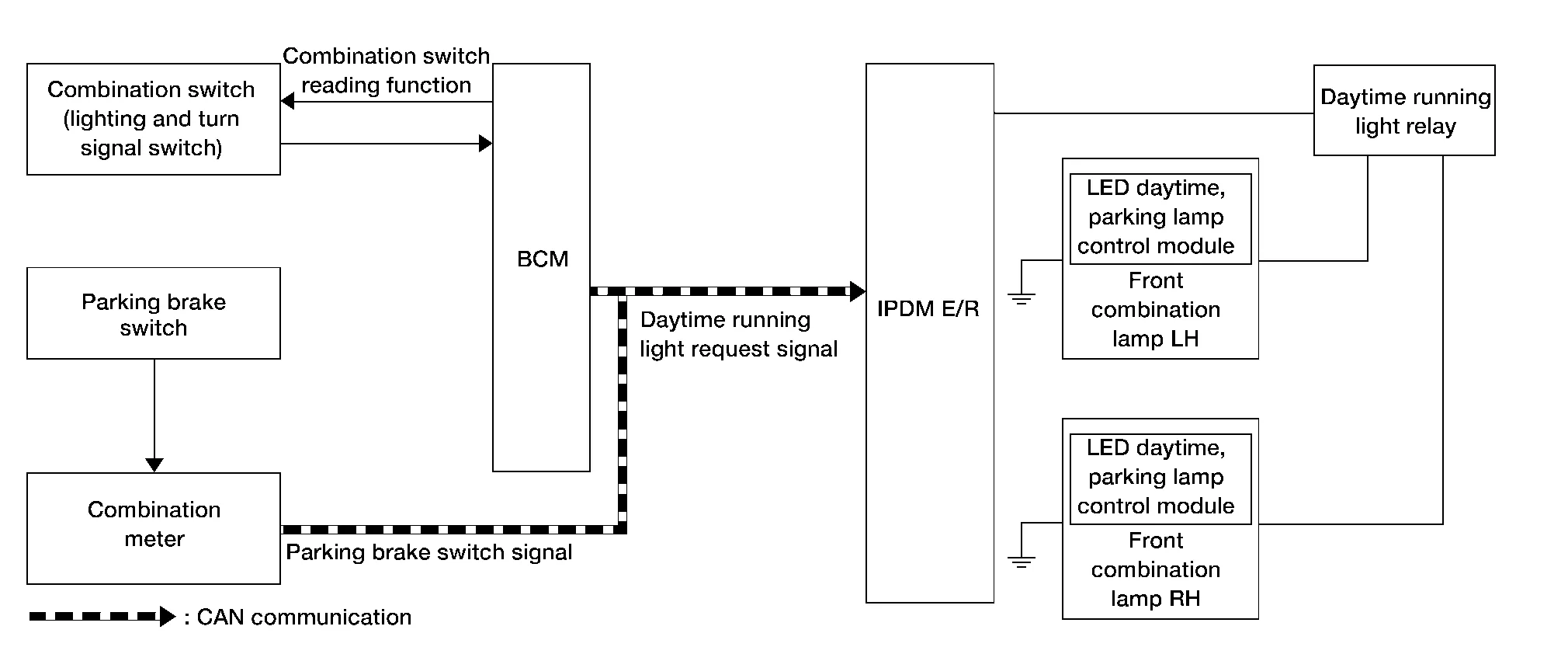
Signal transmission function list
| Signal name | Input | Output | Description |
|---|---|---|---|
| Combination switch signal | Combination switch (lighting and turn signal switch) | BCM | Transmits the combination switch signal to the BCM. |
| Parking brake switch signal | Parking brake switch | Combination meter | Transmits the parking brake switch signal to the combination meter. |
| Parking brake switch signal | Combination meter | BCM (CAN) | Transmits the parking brake switch signal via CAN communication. |
| Daytime running light request signal | BCM | IPDM E/R (CAN) | Transmits the daytime running light request signal via CAN communication. |
OUTLINE
-
Turns the front combination lamps on through the LED daytime, parking lamp control module as the daytime running light.
-
Daytime running light is controlled by daytime running light control function and combination switch reading function of BCM, and relay control function of IPDM E/R.
DAYTIME RUNNING LIGHT OPERATION
-
BCM detects the combination switch (lighting and turn signal switch) condition by the combination switch reading function.
-
BCM detects the Nissan Murano vehicle condition according to ignition switch.
-
BCM detects the parking brake condition by the parking brake switch signal received from combination meter via CAN communication.
-
BCM transmits the daytime running light request signal to IPDM E/R via CAN communication according to the daytime running light ON condition.
Daytime running light ON condition:
-
Ignition switch ON
-
Lighting switch OFF or 1ST
-
Lighting switch AUTO, and the auto light function OFF judgment
-
Parking brake switch OFF
-
-
IPDM E/R controls the daytime running light relay (ground-side) to turn ON according to the daytime running light request signal.
-
Power is supplied from the daytime running light relay to front combination lamp RH and LH, and then daytime running lamps are illuminated.
 High Beam Assist System
System Description
SYSTEM DIAGRAMSignal transmission function list Signal name Input Output Description
Combination switch signal
Combination switch (lighting and turn signal switch)
BCM
Transmits the combination switch signal to the BCM...
 Turn Signal and Hazard Warning Lamp System
System Description
SYSTEM DIAGRAMSignal transmission function list Signal name Input Output Description
Combination switch signal
Combination switch (lighting and turn signal switch)
BCM
Transmits the combination switch signal to the BCM...
Other information:
Nissan Murano (Z52) 2015-2024 Service Manual: Diagnosis System (combination Meter)
On Board Diagnosis Function COMBINATION METER SELF-DIAGNOSIS MODEThe following meter functions can be checked during Combination Meter Self-Diagnosis Mode: Pointer sweep of speedometer, tachometer and gauges Illumination of all LCD segments and color patterns for meter displays Illumination of all lamps/LEDs that are controlled by the combination meter (regardless of switch status) STARTING COMBINATION METER SELF-DIAGNOSIS MODENOTE: Check combination meter power supply and ground circuits if self-diagnosis mode does not start...
Nissan Murano (Z52) 2015-2024 Service Manual: Engine Lubrication System :: System Description. Lubrication System
Engine Lubrication System 1. Camshaft (EXH) journal (No. 1) 2. Timing chain tensioner (secondary) 3. Camshaft (EXH) 4. Camshaft (INT) journal (No. 2) 5. Camshaft (INT) 6. Cylinder head (bank 2) 7. Main oil gallery 8. Upper oil pan 9...
Categories
- Manuals Home
- Nissan Murano Owners Manual
- Nissan Murano Service Manual
- Tire rotation
- Shift lock release
- Memory storage function (key-link)
- New on site
- Most important about car
Luggage hooks

When securing items using luggage hooks located on the back of the seat or side finisher do not apply a load over more than 6.5 lbs. (29 N) to a single hook.
The luggage hooks that are located on the floor should have loads less than 110 lbs. (490 N) to a single hook.