Nissan Murano: System Description / Component Parts. Driver Assistance System
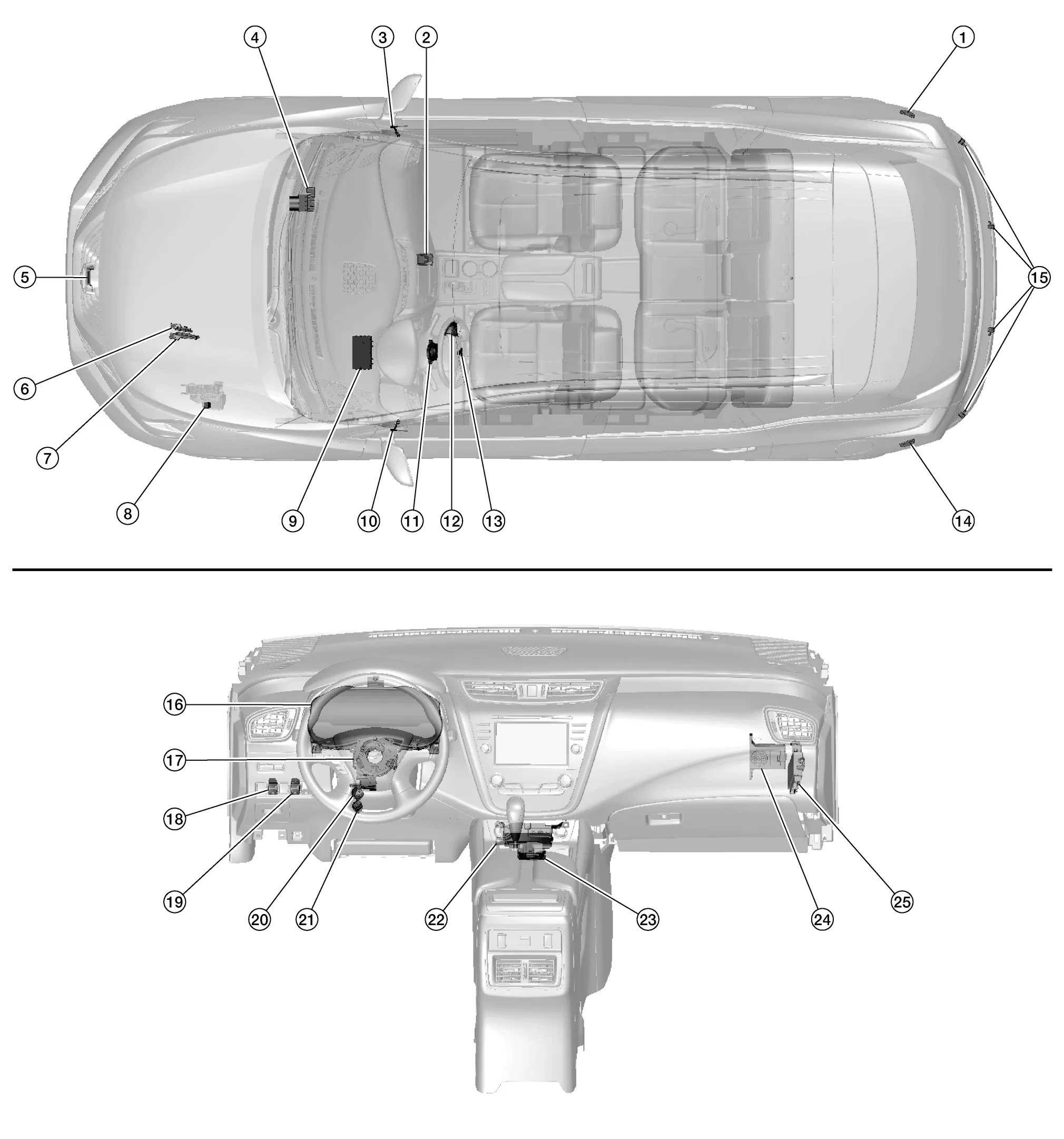
| No. | Component | Function |
|---|---|---|
| 1. | Side radar RH | Refer to Side Radar LH/RH. |
| 2. | Lane camera unit | Refer to Lane Camera Unit. |
| 3. | Blind Spot Warning indicator RH | Refer to Blind Spot Warning Indicator LH/RH. |
| 4. | ABS (Anti-lock Braking System) actuator and electric unit (control unit) |
|
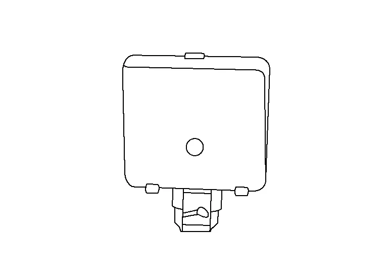
| 5. | Distance sensor | Refer to Distance Sensor. |
| 6. | TCM (Transmission Control Module) |
TCM transmits the signal related to CVT control to ADAS control unit. Refer to Component Parts Location for detailed component location. |
| 7. | ECM (Engine Control Module) |
ECM transmits the stop lamp and brake pedal position switch signals, ICC steering switch signal, etc. to ADAS control unit via CAN communication Refer to Component Parts Location for detailed component location. |
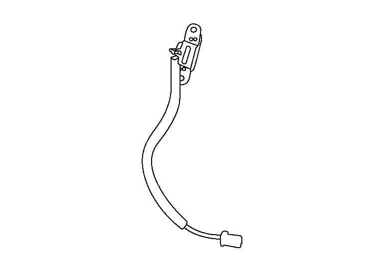
| 8. | ICC brake hold relay (if equipped) | Refer to ICC Brake Hold Relay. |
| 9. | BCM (Body Control Module) |
Transmits the turn indicator signal and position light request signal to ADAS control unit via CAN communication. Refer to Component Parts Location for detailed component location. |
| 10. | Blind Spot Warning indicator LH | Refer to Blind Spot Warning Indicator LH/RH. |
| 11. | Steering angle sensor |
Measures the rotation amount, rotation speed, and rotation direction of the steering wheel and then transmits this signal to the ADAS control unit via CAN communication. Refer to Component Parts Location for detailed component location. |
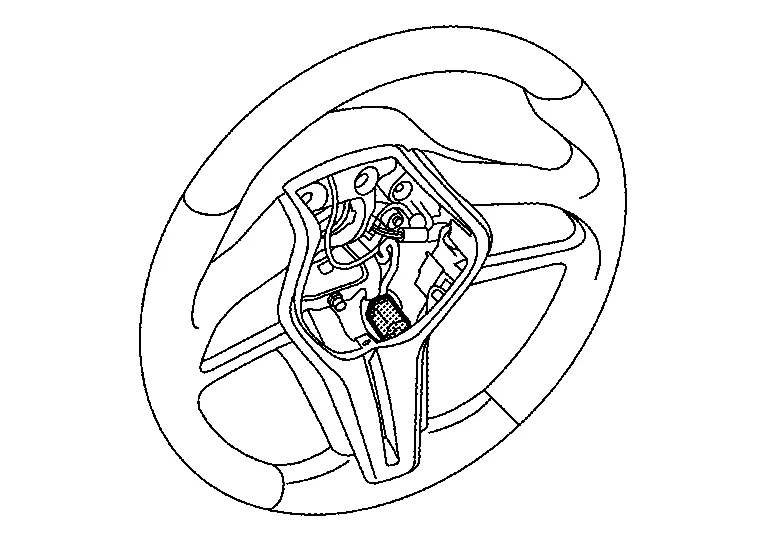
| 12. | ICC (Intelligent Cruise Control) steering switch (if equipped) | Refer to ICC Steering Switch. |
| 13. | Steering vibration motor | Refer to Steering Vibration Motor. |
| 14. | Side radar LH | Refer to Side Radar LH/RH. |
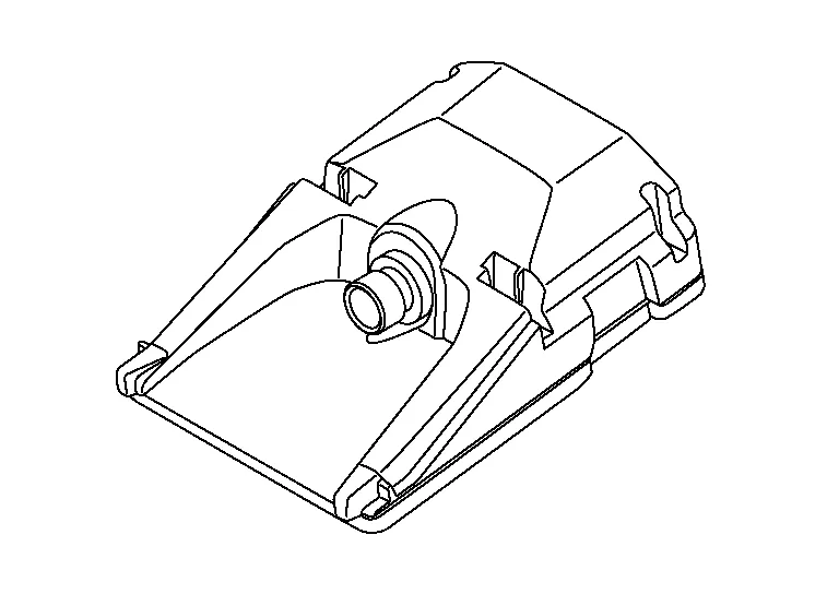
| 15. | Rear sonar sensors | Refer to Sonar Sensor. |
| 16. | Combination meter |
Performs the following operations using the signals received from the ADAS control unit via the CAN communication:
|
| 17. | Combination switch (spiral cable) | Provides a pass-through for the ICC steering switch signal from the ICC steering switch to the ECM. |
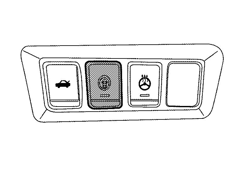
| 18. | VDC (Nissan Murano Vehicle Dynamic Control) OFF switch | Refer to VDC OFF Switch. |
| 19. | LDP (Lane Departure Prevention) switch | Refer to LDP Switch. |
| 20. | Brake pedal position switch | Refer to Brake Pedal Position Switch/Stop Lamp Switch. |
| 21. | Stop lamp switch | |
| 22. | Around View® Monitor control unit |
Receives a RAB warning signal to indicate a red frame on the display. Refer to Around View Monitor Control Unit. |
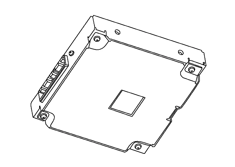
| 23. | ADAS (Advanced Driver Assistance System) control unit |
|
| 24. | Driver assistance buzzer | Refer to Driver Assistance Buzzer. |
| 25. | Sonar control unit | Refer to Sonar Control Unit. |
-
Distance sensor is installed behind the front bumper and detects a vehicle ahead by using millimeter waves.

-
Distance sensor detects radar reflected from a Nissan Murano vehicle ahead by irradiating radar forward and calculates a distance from the vehicle ahead and relative speed, based on the detected signal.
-
Distance sensor transmits the presence/absence of Nissan Murano vehicle ahead and the distance from the vehicle to ADAS control unit via ITS communication.
-
ICC steering switch is installed to the steering wheel and allows the driver to operate the ICC system by using this switch.
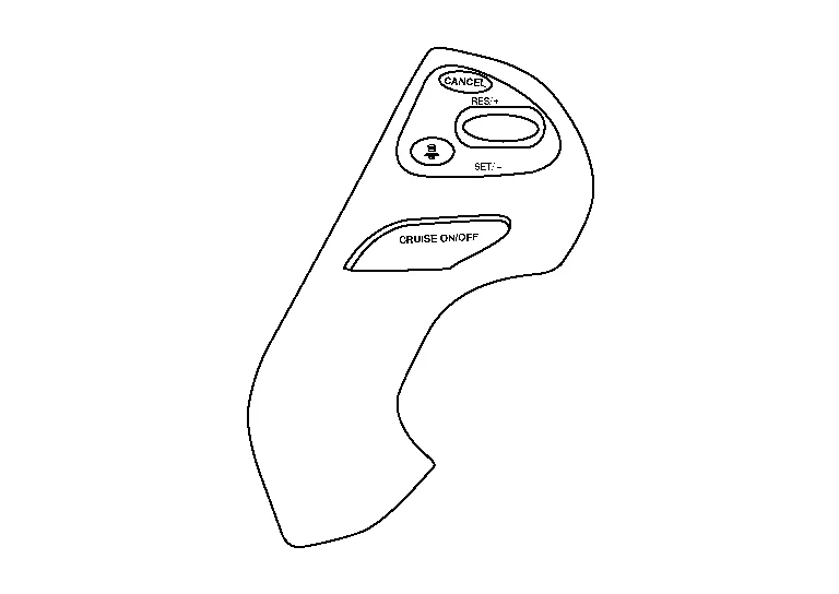
-
ICC steering switch allows the ON/OFF of the Intelligent Cruise Control and the settings of a Nissan Murano vehicle speed and distance between vehicles.
-
ICC steering switch signal is transmitted to ECM. ECM transmits the signal to the ADAS control unit via CAN communication.
-
Brake pedal position switch is installed at the upper part of the brake pedal and detects a brake operation performed by the driver.

-
Brake pedal position switch is turned OFF when depressing the brake pedal.
-
Brake pedal position switch signal is input to ECM. Brake pedal position switch signal is transmitted from ECM to ADAS control unit via CAN communication.
-
Stop lamp switch is installed at the lower part of the brake pedal and detects a brake operation performed by the driver.

-
Stop lamp switch is turned ON, when depressing the brake pedal.
-
Stop lamp switch signal is input to ECM and ABS actuator and electric unit (control unit). Stop lamp switch signals are transmitted from ECM and ABS actuator and electric unit (control unit) to ADAS control unit via CAN communication.
-
ICC brake hold relay is installed in the engine room (left side).

-
When the brake is activated by the system, the ICC brake hold relay turns ON the stop lamp by bypassing the circuit of the stop lamp, according to a signal transmitted from the ADAS control unit.
-
Receives meter display signal from ADAS control unit via CAN communication.
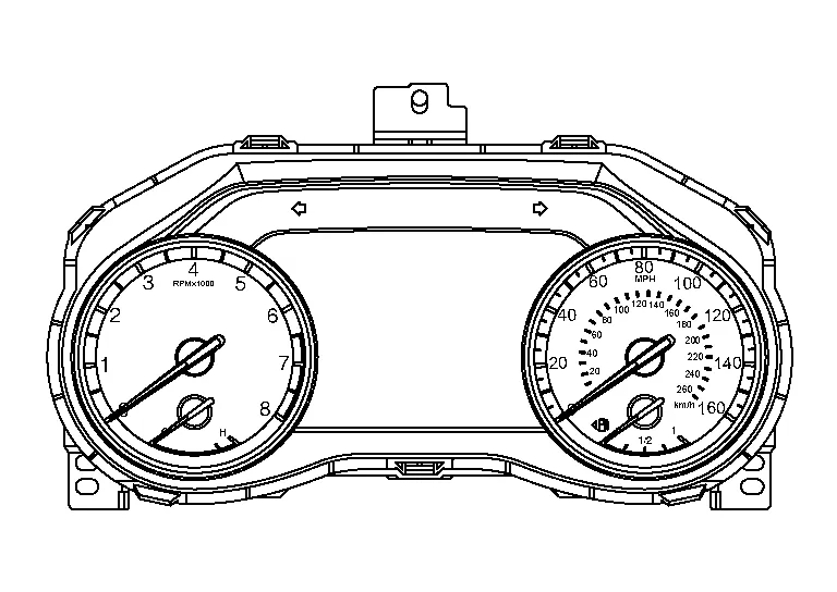
-
Displays the system status according to a signal received from the ADAS control unit.
-
Receives a buzzer output signal via CAN communication and sounds the buzzer.
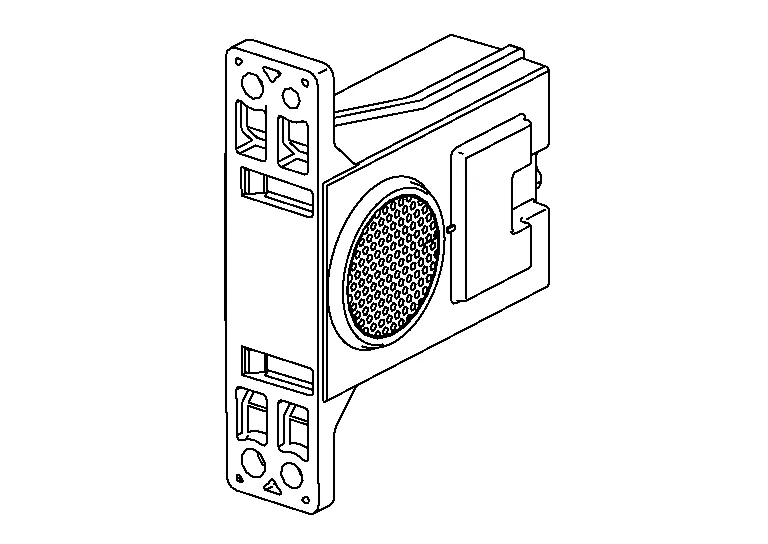
-
The driver assistance buzzer is installed behind the glove box assembly and housing assembly.
-
When a warning buzzer signal is received from the ADAS control unit, the buzzer sounds.
-
Installed near the rear bumper, the side radar detects other vehicles beside own vehicle in an adjacent lane.
-
Connected with the ADAS control unit via ITS communication, the side radar transmits a Nissan Murano vehicle detection signal.
-
Receives a Blind Spot Warning indicator signal and a Blind Spot Warning indicator dimmer signal from the ADAS control unit and transmits an indicator operation signal to the Blind Spot Warning indicator LH/RH.
-
Since side radar RH and side radar LH have the same specifications, side radar RH has the right/left switching signal circuit for identification.
-
Installed on the front door corner cover, the Blind Spot Warning indicator warns the driver by lighting/blinking.
-
Receives a Blind Spot Warning indicator operation signal from the side radar LH/RH and blinks or turns ON/OFF the Blind Spot Warning indicator.
-
The steering vibration motor is installed inside the steering wheel.
-
When a motor operation signal is received the ADAS control unit activates the steering vibration motor.
-
Installed on the LH side of the instrument lower panel, the LDP switch is used to active/deactivate the I-LI system.
-
LDP switch (ON/OFF) is input to ADAS control unit.
-
Lane camera unit is installed to the windshield and detects the lane marker in travel lane and pedestrian ahead.
-
Transmits lane marker signal to ADAS control unit via ITS communication.
-
Sonar sensors are installed in the rear bumper fascia.
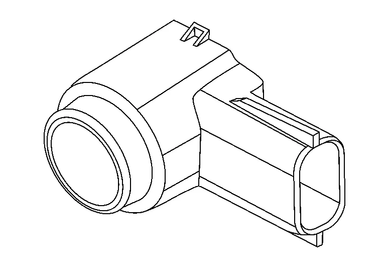
-
When a distance from an obstacle is detected, a signal is transmitted to the sonar control unit.
-
Sonar control unit is installed behind the LH instrument panel finisher.
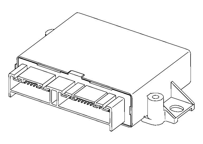
-
Based on signals received from the rear sonar sensors, the sonar control unit sends the distance signal to the ADAS control unit via CAN communication for RAB operation.
-
The around view monitor control unit is installed to the center of the instrument panel.
-
The around view monitor control unit receives the sonar sensor distance signals used for Rear Automatic Braking (RAB) operation.

 System
..
Other information:
Nissan Murano (Z52) 2015-2024 Service Manual: Rear Suspension :: Unit Disassembly and Assembly. Rear Shock Absorber
Exploded View 1. Rear shock absorber 2. Piston rod lock nut 3. Shock absorber insulator 4. Bound bumper Front Disassembly and Assembly DISASSEMBLYCAUTION: Do not damage the shock absorber piston rod when removing components from the shock absorber...
Nissan Murano (Z52) 2015-2024 Service Manual: Meter System
System Description SYSTEM DIAGRAMCombination Meter Input Signal (CAN Communication Signal) Transmit unit Signal name ABS actuator and electric unit (control unit) Nissan Murano Vehicle speed signal ABS warning lamp signal VDC warning lamp signal VDC OFF indicator lamp signal Brake warning lamp signal BCM Dimmer signal Position light request signal Door switch signal Front fog light request signal High beam request signal Meter display signal Sleep wake up signal Buzzer output signal Tire pressure data signal Key ID signal Turn indicator signal TPMS malfunction warning lamp signal Starter relay status signal Low tire pressure warning lamp signal TCM Shift position signal CVT CHECK warning lamp signal ECM Engine speed signal ASCD status signal Engine coolant temperature signal Fuel consumption monitor signal Malfunctioning indicator lamp signal Engine status signal Engine oil pressure sensor signal Fuel-filler cap warning display signal AWD control unit (if equipped) AWD warning lamp signal A/C auto amp...
Categories
- Manuals Home
- Nissan Murano Owners Manual
- Nissan Murano Service Manual
- Turning the AEB system on/off
- GAS STATION INFORMATION
- Rear bench seat adjustment
- New on site
- Most important about car
Fuel gauge

The gauge indicates the approximate fuel level in the tank.
The gauge may move slightly during braking, turning, acceleration, or going up or down hills.
The gauge needle returns to 0 (Empty) after the ignition switch is placed in the OFF position.