Nissan Murano: System / Combination Switch Reading System
SYSTEM DIAGRAM

OUTLINE
-
BCM reads the status of the combination switch (light, turn signal, wiper and washer) and recognizes the status of each switch.
-
BCM has a combination of 5 output terminals (OUTPUT 1 - 5) and 5 input terminals (INPUT 1 - 5) and reads a maximum of 19 switch states.
COMBINATION SWITCH MATRIX

| System | INPUT 1 | INPUT 2 | INPUT 3 | INPUT 4 | INPUT 5 |
|---|---|---|---|---|---|
| OUTPUT 1 | — | FR WASHER | FR WIPER LOW | TURN LH | TURN RH |
| OUTPUT 2 | FR WIPER HI | — | FR WIPER INT/AUTO | PASSING | HEADLAMP 1 |
| OUTPUT 3 | INT VOLUME 1 | RR WASHER | — | HEADLAMP 2 | HI BEAM |
| OUTPUT 4 | RR WIPER INT | INT VOLUME 3 | AUTO LIGHT | — | TAIL LAMP |
| OUTPUT 5 | INT VOLUME 2 | RR WIPER ON | — | FR FOG | — |
COMBINATION SWITCH READING FUNCTION
Description
-
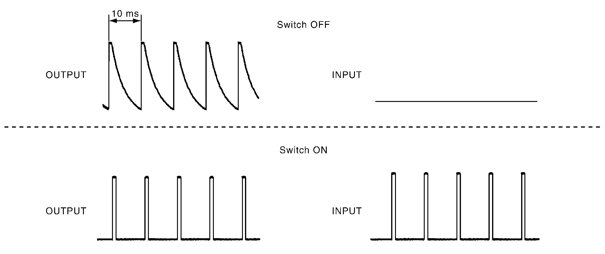
BCM reads the status of the combination switch at 10 ms intervals normally.
 NOTE:
NOTE:
BCM reads the status of the combination switch at 60 ms intervals when BCM is controlled at low power consumption control mode.
-
BCM operates as follows and judges the status of the combination switch.
-
It operates the transistor on OUTPUT side in the following order: OUTPUT 1 → 2 → 3 → 4 → 5, and outputs voltage waveform.
-
The voltage waveform of OUTPUT corresponding to the formed circuit is input into the interface on INPUT side if any (1 or more) switches are ON.
-
It reads this change of the voltage as the status signal of the combination switch.

-
Operation Example
In the following operation example, the combination of the status signals of the combination switch is replaced as follows: INPUT 1 - 5 to “1 - 5” and OUTPUT 1 - 5 to “A - E”.
Example 1: When a switch (TAIL LAMP) is turned ON
-
The circuit between OUTPUT 4 and INPUT 5 is formed when the TAIL LAMP switch is turned ON.

-
BCM detects the combination switch status signal “5D” when the signal of OUTPUT 4 is input to INPUT 5.
-
BCM judges that the TAIL LAMP switch is ON when the signal “5D” is detected.
Example 2: When some switches (TURN RH, TAIL LAMP) are turned ON
-
The circuits between OUTPUT 1 and INPUT 5 and between OUTPUT 4 and INPUT 5 are formed when the TURN RH switch and TAIL LAMP switch are turned ON.

-
BCM detects the combination switch status signal “5AD” when the signals of OUTPUT 1 and OUTPUT 4 are input to INPUT 5.
-
BCM judges that the TURN RH switch and TAIL LAMP switch are ON when the signal “5AD” is detected.
WIPER INTERMITTENT DIAL POSITION SETTING (FRONT WIPER INTERMITTENT OPERATION)
BCM judges the wiper intermittent dial 1 - 7 by the status of INT VOLUME 1, 2, and 3 switches.
|
Wiper intermittent dial position | Switch status | ||
|---|---|---|---|
| INT VOLUME 1 | INT VOLUME 2 | INT VOLUME 3 | |
| 1 | ON | ON | ON |
| 2 | ON | ON | OFF |
| 3 | ON | OFF | OFF |
| 4 | OFF | OFF | OFF |
| 5 | OFF | OFF | ON |
| 6 | OFF | ON | ON |
| 7 | OFF | ON | OFF |
 Body Control System
System Description
OUTLINE
BCM controls various electrical components. It receives the information required from CAN communication and the signals received from each switch and sensor...
 Signal Buffer System
System Description
SYSTEM DIAGRAMOUTLINEBCM has the signal transmission function that outputs/transmits each input/received signal to each unit.Signal transmission function list Signal name Input Output Description
Push-button ignition switch signal
Push-button ignition switch
BCM
Transmits the push-button ignition switch signal to the BCM...
Other information:
Nissan Murano (Z52) 2015-2024 Service Manual: P0327 Ks
DTC Description DTC DETECTION LOGIC An excessively low voltage from the sensor is sent to ECM. An excessively high voltage from the sensor is sent to ECM. DTC CONSULT screen terms (Trouble diagnosis content) DTC detection condition P0327 KNOCK SEN/CIRC-B1 (Knock sensor 1 circuit low bank 1) Diagnosis condition Start engine and let it idle Signal (terminal) Voltage signal transmitted from knock sensor to ECM Threshold An excessively low voltage from the sensor is sent to ECM Diagnosis delay time — P0328 KNOCK SEN/CIRC-B1 (Knock sensor 1 circuit high bank 1) Diagnosis condition Start engine and let it idle Signal (terminal) Voltage signal transmitted from knock sensor to ECM Threshold An excessively high voltage from the sensor is sent to ECM...
Nissan Murano (Z52) 2015-2024 Service Manual: Normal Operating Condition
Description RELATED TO NOISEThe majority of the audio concerns are the result of outside causes (bad CD, electromagnetic interference, etc.).The following noise results from variations in field strength, such as fading noise and multi-path noise, or external noise from trains and other sources...
Categories
- Manuals Home
- Nissan Murano Owners Manual
- Nissan Murano Service Manual
- System malfunction
- Intelligent Forward Collision Warning (I-FCW)
- Vehicle Dynamic Control (VDC) OFF switch
- New on site
- Most important about car
Front manual seat adjustment (if so equipped)
Your vehicle seats can be adjusted manually. For additional information about adjusting the seats, refer to the steps outlined in this section.
Forward and backward