Nissan Murano: Engine Mechanical :: Periodic Maintenance / Camshaft Valve Clearance
CHECKING
CAUTION:
Check valve clearance while engine is cold and not running.
 NOTE:
NOTE:
Perform valve clearance inspection after removal, installation or replacement of camshaft or valve parts, or as necessary.
-
Remove the air duct with air cleaner case, collectors, hoses, wires, harnesses, and connectors. Refer to Removal and Installation.
-
Remove the intake manifold collector. Refer to Removal and Installation.
-
Remove the ignition coils and spark plugs. Refer to Exploded View.
-
Remove the rocker covers. Refer to Exploded View.
-
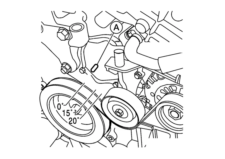
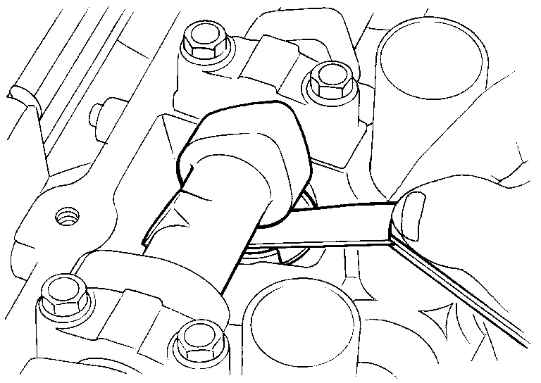
Set No.1 cylinder at TDC on its compression stroke.

: Engine front -
Align pointer with TDC mark (A) on crankshaft pulley.
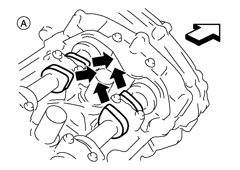
-
Check that the valve lifters on No.1 cylinder, bank 1 (A) are loose and valve lifters on No.4 are tight. If not, turn the crankshaft one full revolution (360°) and align as shown.
-
| : Engine front |
-
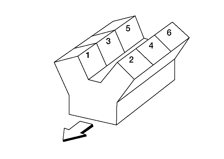
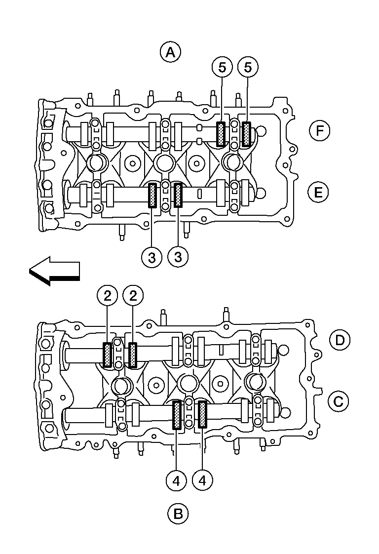
Check only the valves as shown.
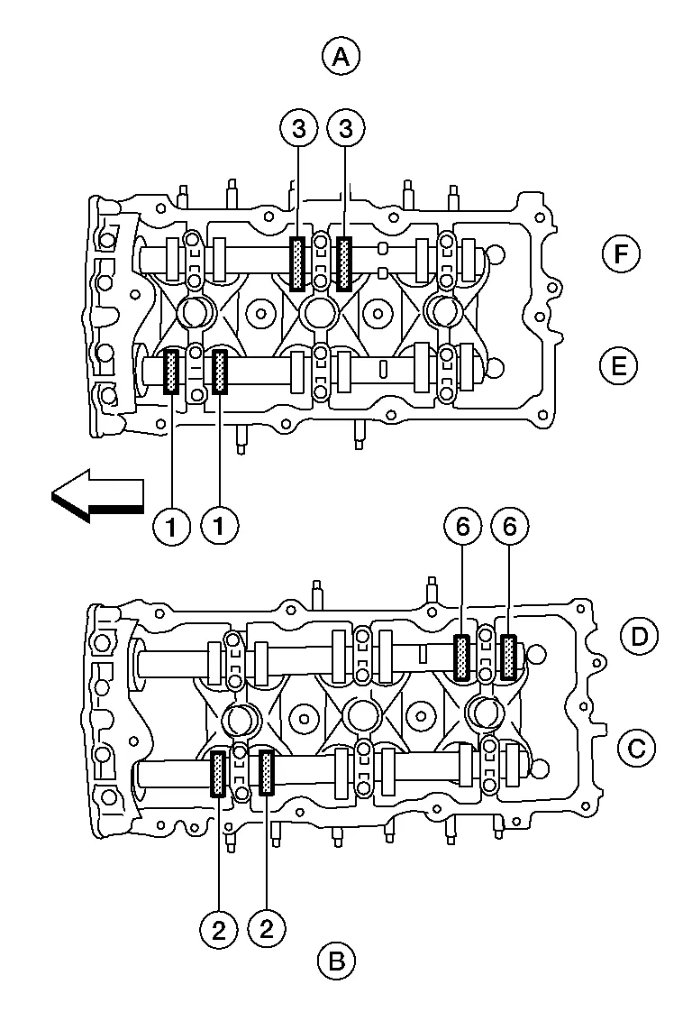
Crank Position Valve No. 1 Valve No. 2 Valve No. 3 Valve No. 6 No. 1 TDC Intake Exhaust Exhaust Intake (A) : Bank 1 cylinder head (B) : Bank 2 cylinder head (C) : Bank 2 exhaust camshaft (D) : Bank 2 intake camshaft (E) : Bank 1 intake camshaft (F) : Bank 1 exhaust camshaft : Engine front -
Using a feeler gauge, measure the clearance between the valve lifter and camshaft.
Valve clearance : Refer to General Specification. -
Record any valve clearance measurements which are out of specification. They will be used later to determine the required replacement lifter size.
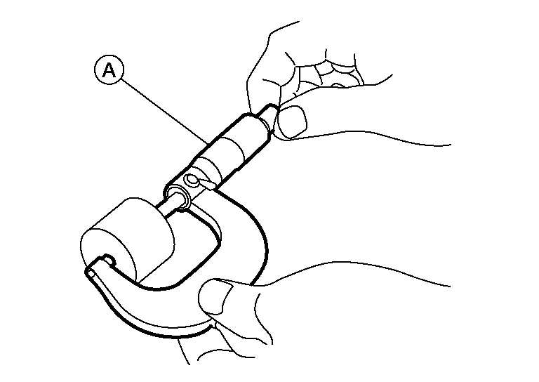
(A) : Camshaft (B) : Valve lifter (C) : Suitable tool 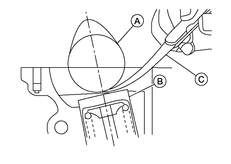
-
-
Turn crankshaft 240°.
-
Set No.3 cylinder at TDC on its compression stroke.
-
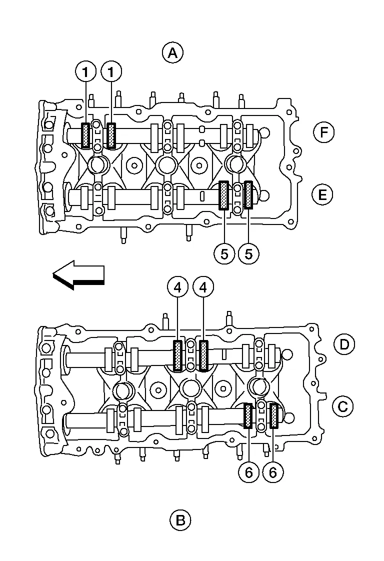
Check only those valves as shown.
Crank Position Valve No. 2 Valve No. 3 Valve No. 4 Valve No. 5 No. 3 TDC Intake Intake Exhaust Exhaust (A) : Bank 1 cylinder head (B) : Bank 2 cylinder head (C) : Bank 2 exhaust camshaft (D) : Bank 2 intake camshaft (E) : Bank 1 intake camshaft (F) : Bank 1 exhaust camshaft : Engine front -
Turn the crankshaft 240° and align as above.
-
Set No.5 cylinder at TDC on its compression stroke.
-
Check only those valves as shown.
Crank Position Valve No. 1 Valve No. 4 Valve No. 5 Valve No. 6 No. 5 TDC Exhaust Intake Intake Exhaust (A) : Bank 1 cylinder head (B) : Bank 2 cylinder head (C) : Bank 2 exhaust camshaft (D) : Bank 2 intake camshaft (E) : Bank 1 intake camshaft (F) : Bank 1 exhaust camshaft : Engine front -
Perform adjustment if the measured values are out of the specification range.
-
Installation of components is in the reverse order of removal.
VALVE ADJUSTING
CAUTION:
Adjust valve clearance while engine is cold.
NOTE:
-
Perform adjustment by selecting the correct head thickness of the valve lifter (adjusting shims are not used).
-
The specified valve lifter thickness dimension is measured at room temperature.
-
Use specifications for hot engine for hot engine condition to confirm valve clearances.
-
Remove the camshaft.
-
Remove the valve lifter that was measured as being outside the standard specifications.
-
Measure the center thickness of the removed lifter with suitable tool (A) as shown.
-
Use the equation below to calculate the replacement valve lifter thickness.
Valve lifter thickness calculation: (C1 – C2) + t1=t C1 = measured valve clearance C2 = standard valve clearance t1 = thickness of the removed lifter t = thickness of the replacement lifter -
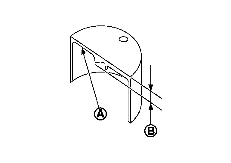
The thickness of the new valve lifter can be identified by the stamp mark (A) on the reverse side (inside the lifter).
 NOTE:
NOTE:
Available thicknesses of the valve lifters (B) are: 3.00 - 3.50 mm (0.1181 - 0.1378 in), in 0.02 mm (0.0008 in) increments. Refer to Camshaft.
-
-
Install the selected replacement valve lifter.
-
Install the camshaft.
-
Rotate the crankshaft a few turns by hand.
-
Confirm that the valve clearances are within specification.
-
After the engine has been run to full operating temperature, confirm that the valve clearances are within specification.
Standard Valve Clearance Cold1 (reference data) Hot2 (reference data) Intake 0.26 - 0.34 mm (0.010 - 0.013 in) 0.304 - 0.416 mm (0.012 - 0.016 in) Exhaust 0.29 - 0.37 mm (0.011 - 0.015 in) 0.308 - 0.432 mm (0.012 - 0.017 in) 1 : Approximately 20°C (68°F)
2 : Approximately 80°C (176°F)
 Spark Plug
Exploded View
1.
Ignition coil
2.
Spark plug
3.
Rocker cover (RH)
4.
Rocker cover (LH)
Front
Removal and Installation
REMOVALRemove the ignition coil...
 Compression Pressure
On-Vehicle Service
CHECKING COMPRESSION PRESSURERun the engine until it reaches normal operating temperature.
Turn the ignition switch to OFF.
Release fuel pressure and leave the fuel pump electrically disconnected...
Other information:
Nissan Murano (Z52) 2015-2024 Owners Manual: Moving Object Detection (MOD) (if so equipped)
CAMERA button WARNING Failure to follow the warnings and instructions for proper use of the Moving Object Detection (MOD) system could result in serious injury or death. The MOD system is not a substitute for proper vehicle operation and is not designed to prevent contact with objects surrounding the vehicle...
Nissan Murano (Z52) 2015-2024 Service Manual: P2271 Ho2s2
DTC Description DTC DETECTION LOGICThe heated oxygen sensor 2 has a much longer switching time between rich and lean than the air fuel ratio (A/F) sensor 1. The oxygen storage capacity of the three way catalyst (manifold) causes the longer switching time...
Categories
- Manuals Home
- Nissan Murano Owners Manual
- Nissan Murano Service Manual
- Memory storage function (key-link)
- All-Wheel Drive (AWD) (if so equipped)
- Warning lights
- New on site
- Most important about car
Seatback pockets

Theremaybe one or two seatback pockets located on the back of the driver and passenger seats. The pockets can be used to store maps.
WARNING