
Nissan Murano: Removal and Installation / Bcm
CAUTION:
-
Before replacing the BCM, perform “READ CONFIGURATION” to save or print current Nissan Murano vehicle specification. Refer to Description.
-
When replacing the BCM, a new BCM must be used. The functions controlled by the BCM do not operate properly if a BCM from another Nissan Murano vehicle is used.
REMOVAL
Disconnect the negative battery terminal. Refer to Removal and Installation.
Remove the combination meter. Refer to Removal and Installation.
Remove the BCM bolts.
Disconnect the harness connectors from the BCM (1) and remove.
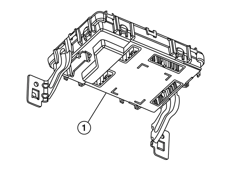
INSTALLATION
Installation is in the reverse order of removal.
CAUTION:
-
When replacing BCM, perform “WRITE CONFIGURATION”. Refer to Description.
-
When replacing BCM, perform the system initialization (NATS). Refer to Description.
-
When replacing BCM, if new BCM does not come with key fobs attached, all existing key fobs must be re-registered.
-
For initialization and registration of Intelligent Keys, refer to CONSULT Immobilizer mode and follow the on-screen instructions.

 Combination Switch
Exploded View
1.
Combination switch
2.
Combination switch harness connector
Removal and Installation
REMOVALDisconnect both the negative and positive battery terminals, then wait at least three minutes...
Other information:
Nissan Murano (Z52) 2015-2024 Service Manual: Engine Mechanical :: System Description. Noise, Vibration, and Harshness (nvh) Troubleshooting
NVH Troubleshooting - Engine Noise 1. Camshaft bearing noise 2. Piston pin noise 3. Piston slap noise 4. Main bearing noise 5. Connecting rod bearing noise 6. Water pump noise 7. Timing chain and chain tensioner noise 8...
Nissan Murano (Z52) 2015-2024 Service Manual: Back-Up Lamp System
System Description SYSTEM DIAGRAMSignal transmission function list Signal name Input Output Description Reverse signal Transmission range switch TCM Transmits the reverse signal to the TCM. Reverse signal TCM BCM (CAN) Transmits the reverse signal via CAN communication...
Categories
- Manuals Home
- Nissan Murano Owners Manual
- Nissan Murano Service Manual
- Passenger compartment
- Shift lock release
- Indicator lights
- New on site
- Most important about car
Seatback pockets
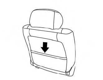
Theremaybe one or two seatback pockets located on the back of the driver and passenger seats. The pockets can be used to store maps.
WARNING
