Nissan Murano: Removal and Installation / Audio Unit
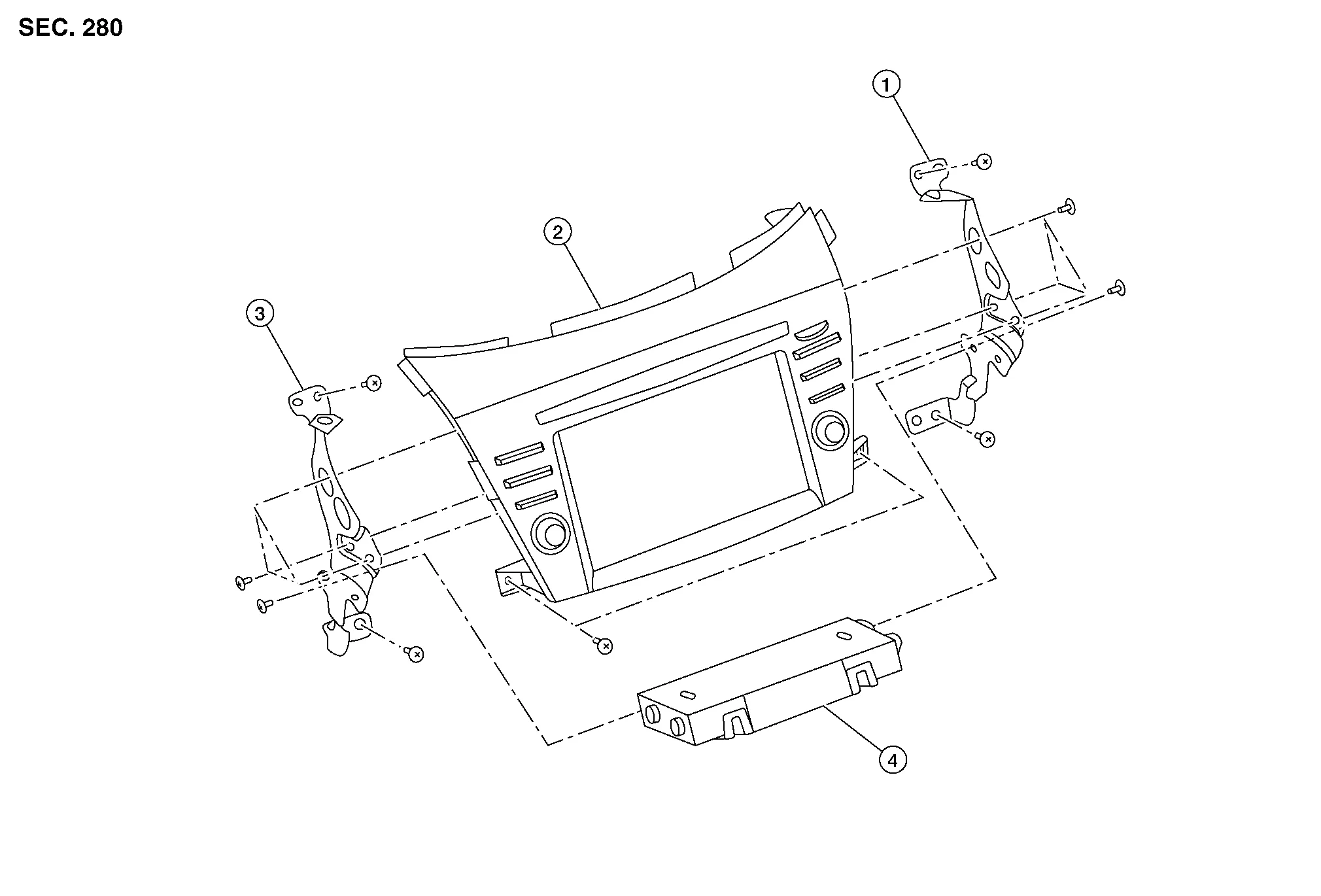
| 1. | Audio unit bracket (RH) | 2. | Audio unit | 3. | Audio unit bracket (LH) |
| 4. | A/C auto amp. |
REMOVAL
CAUTION:
Before disconnecting the audio unit and battery terminals, turn the ignition switch OFF and wait at least 30 seconds.
 NOTE:
NOTE:
-
Before replacing audio unit, perform “Before Replace ECU” of “Read / Write Configuration” to save or print current Nissan Murano vehicle specification. Refer to Description.
-
After the ignition switch is turned OFF, the audio unit continues operating for approximately 30 seconds.
-
Therefore, data corruption may occur if battery voltage is cut off within 30 seconds.
Disconnect the negative battery terminal. Refer to Removal and Installation.
Remove cluster lid D. Refer to Removal and Installation.
Remove A/C switch assembly. Refer to Removal and Installation.
Remove audio unit screws then pull out audio unit.
Disconnect the harness connectors from audio unit and remove.
Remove audio unit bracket (LH/RH) screws and audio unit brackets [(LH/RH) (if necessary)].
INSTALLATION
CAUTION:
Be sure to perform “After Replace ECU” of “Read / Write Configuration” or “Manual Configuration” when replacing audio unit. Refer to Description.
Installation is in the reverse order of removal.

 Steering Switches
Exploded View
1.
Steering wheel
2.
Cover
3.
Steering switches
4.
Driver air bag module
A.
Refer to Exploded View.
Pawl
Removal and Installation
REMOVALNOTE:
The steering switches is serviced as an assembly...
Other information:
Nissan Murano (Z52) 2015-2024 Service Manual: P1614 Chain of Immu-Key
DTC Description DTC DETECTION LOGIC DTC No. CONSULT screen terms (Trouble diagnosis content) DTC Detection Condition P1614 CHAIN OF IMMU-KEY (Chain of immobilizer-key) Diagnosis condition When ignition switch ON. Signal (terminal) — Threshold Inactive communication between NATS antenna amp...
Nissan Murano (Z52) 2015-2024 Owners Manual: Warning signals
To help prevent the vehicle from moving unexpectedly by erroneous operation of the Intelligent Key or to help prevent the vehicle from being stolen, a chime or buzzer sounds from inside and outside the vehicle and a warning is displayed in the instrument panel...
Categories
- Manuals Home
- Nissan Murano Owners Manual
- Nissan Murano Service Manual
- Intelligent Forward Collision Warning (I-FCW)
- Power Steering Fluid (PSF)
- Indicator lights
- New on site
- Most important about car
Unfastening the seat belts. Checking seat belt operation
Unfastening the seat belts

To unfasten the seat belt, press the button
on the buckle  . The seat belt
automatically
retracts.
. The seat belt
automatically
retracts.