Nissan Murano: Driveline :: Transfer: Ty21c / Unit Removal and Installation. Transfer Assembly
 |
Transfer assembly |  |
Transfer gusset |  |
Rear gusset |
 : N·m (kg-m, ft-lb) : N·m (kg-m, ft-lb) |
|||||
 NOTE:
NOTE:
When removing components such as hoses, tubes/lines, etc., cap or plug openings to prevent fluid from spilling.
REMOVAL
Drain the transfer oil. Refer to Draining.
Remove the cowl top and the lower cowl top extension. Refer to Exploded View.
Release clamp and separate reservoir tank hose from reservoir tank. Refer to Exploded View.
Remove reservoir tank. Refer to Exploded View.
Remove engine mounting bracket (front). Refer to Exploded View.
Remove the front wheel and tire (RH) using power tool. Refer to Removal and Installation.
Remove the front under cover. Refer to Removal and Installation.
Remove the fender protector side cover (RH). Refer to Removal and Installation.
Remove engine mounting insulator (front). Refer to Exploded View.
Remove the front exhaust tube, hanger and heat insulator. Refer to Exploded View.
Remove the propeller shaft from the transfer assembly and position aside. Refer to Removal and Installation
Remove the cotter pin.
Remove the nut retainer.
loosen the wheel hub lock nut from the drive shaft using a power tool.
Using a piece of wood and a suitable tool, tap on the wheel hub lock nut to disengage the drive shaft from the wheel hub and bearing.

CAUTION:
-
Do not place the drive shaft joint at an extreme angle. Be careful not to over-extend the slide joint.
-
Do not allow the drive shaft to hang without support.
NOTE:
Use a suitable puller if the drive shaft cannot be separated from the wheel hub and bearing.
Remove the wheel hub lock nut.
Remove the lower strut bolts and nuts.
Separate the front strut from the steering knuckle. Refer to Exploded View.
Remove the bearing retainer to support bearing bracket bolts.
Remove the bearing retainer.
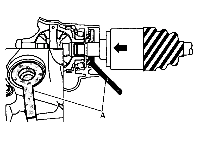
Insert suitable tool (A) between the drive shaft and the transfer assembly. Remove the drive shaft.
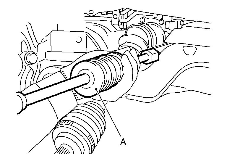
CAUTION:
Do not place the drive shaft joint at an extreme angle when removing the drive shaft. Also be careful not to overextend the slide joint.
| Tool (A) | : Drive shaft joint puller (Commercially available) |
Remove exhaust manifold and three way catalyst heat shields with power tool.
Remove the three way catalyst support bolt (bank 1). Refer to Exploded View.
Disconnect the harness connector from each sensor, and remove the harness from the bracket and middle clamp. Refer to Exploded View.
Remove the three way catalyst (bank 1) by loosening the bolts first and then removing the nuts and through bolts.
Loosen the exhaust manifold nuts in reverse of the order shown.

| : Engine front |
NOTE:
Number 7 and 8 are not applicable to removal.
Remove the exhaust manifold (bank 1).
CAUTION:
Handle carefully to avoid any shock to three way catalyst.
Support transaxle with a suitable jack.
Remove engine mounting insulator (LH). Refer to Exploded View.
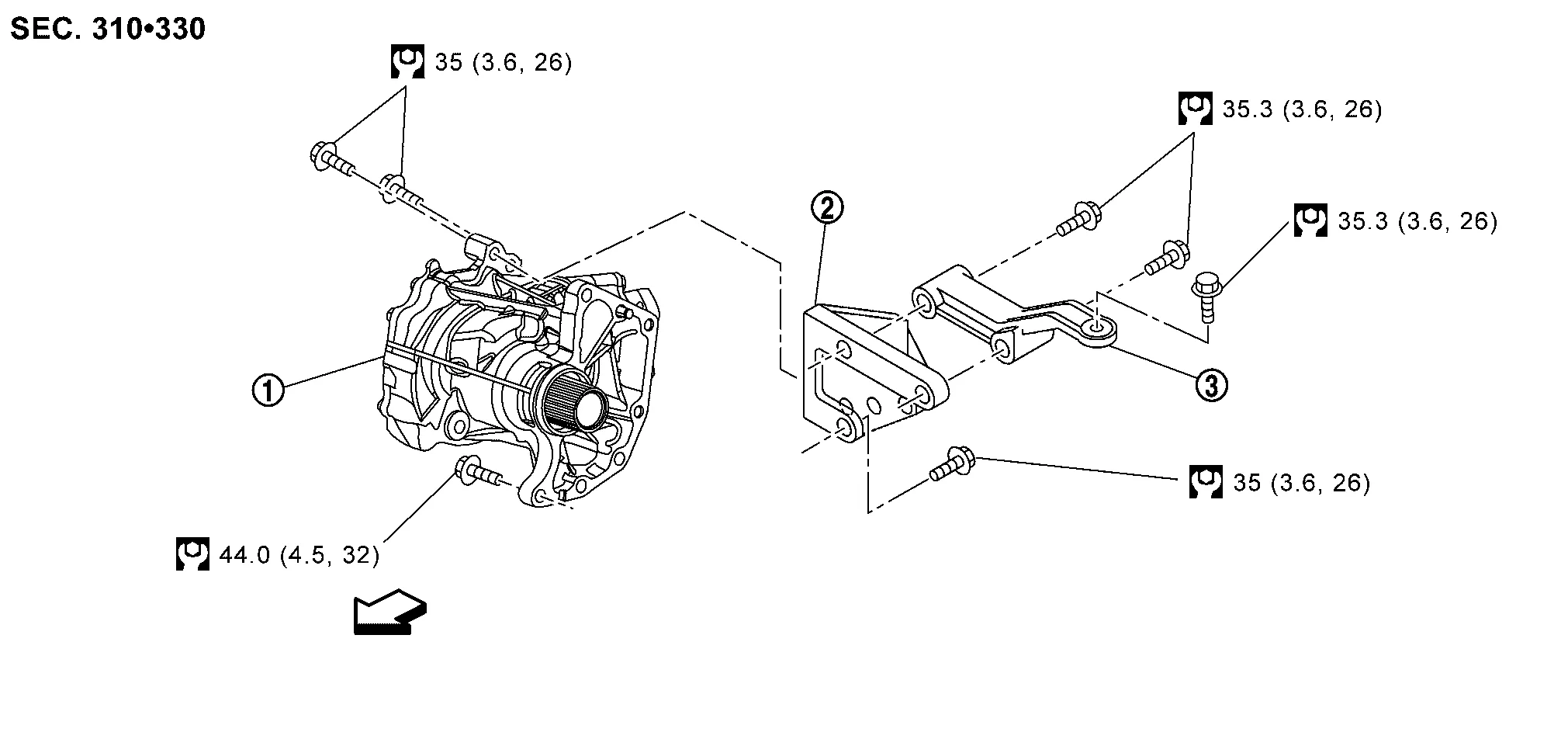
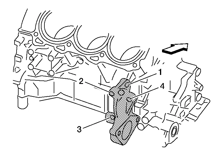
Remove rear gusset and transfer gusset.
Remove transaxle assembly to transfer assembly bolts.
CAUTION:
Be careful not to damage gear ring oil seal inside of CVT.
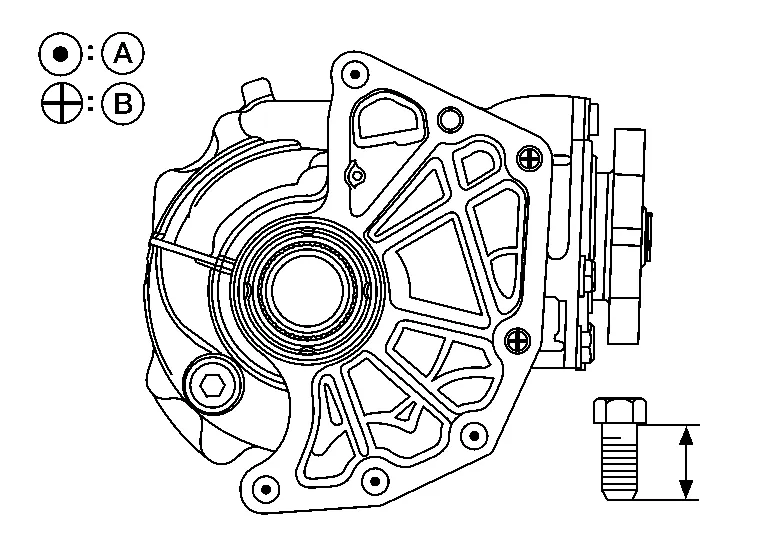
| Bolt No. | (A) | (B) |
|---|---|---|
| Quantity | 4 | 2 |
Bolt length “ ” mm (in) ” mm (in) |
44 (1.73) | 42 (1.65) |
Remove transfer assembly from the Nissan Murano vehicle.
CAUTION:
-
Do not damage air breather hose.
-
After removing transfer from transaxle, always replace differential side oil seal of the transaxle side with new one. Refer to Removal and Installation.
Remove the drive shaft oil seal using the following procedure:Using a suitable tool, remove the transfer cover oil seal.
CAUTION:
-
When removing transfer cover oil seal with suitable tool, do not damage the transfer cover.
-
Do not reuse transfer cover oil seal.
CAUTION:
Do not reuse drive shaft oil seal.
INSTALLATION
Installation is in the reverse order of removal.
-
When installing the transfer to the transaxle, install the bolts following the standard below.
Bolt No. (A) (B) Quantity 4 2 Bolt length “ ” mm (in) 44 (1.73) 42 (1.65) CAUTION:
-
When installing transfer to transaxle, be careful not to damage oil seal of transaxle.
-
Do not reuse differential side oil seal.
-
-
Check transfer oil level and check for transfer oil leaks after installation. Refer to Refilling.
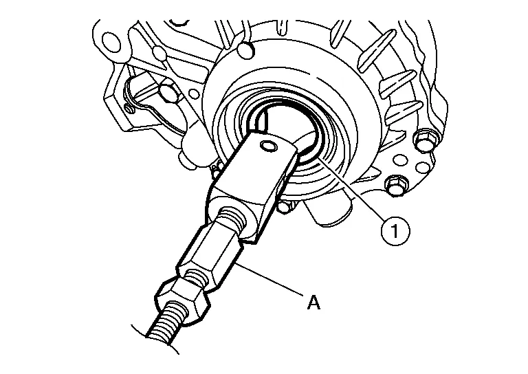
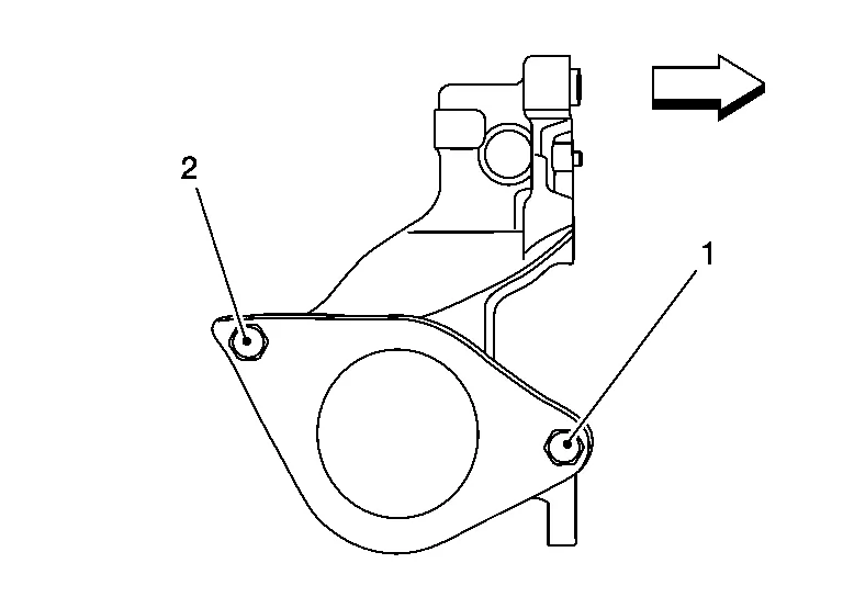
Install the drive shaft oil seal and transfer cover oil seal using the following procedure:Install drive shaft oil seal (1) onto Tool (A) before installing into transfer case assembly using Tool (B).
CAUTION:
Do not reuse drive shaft oil seal.
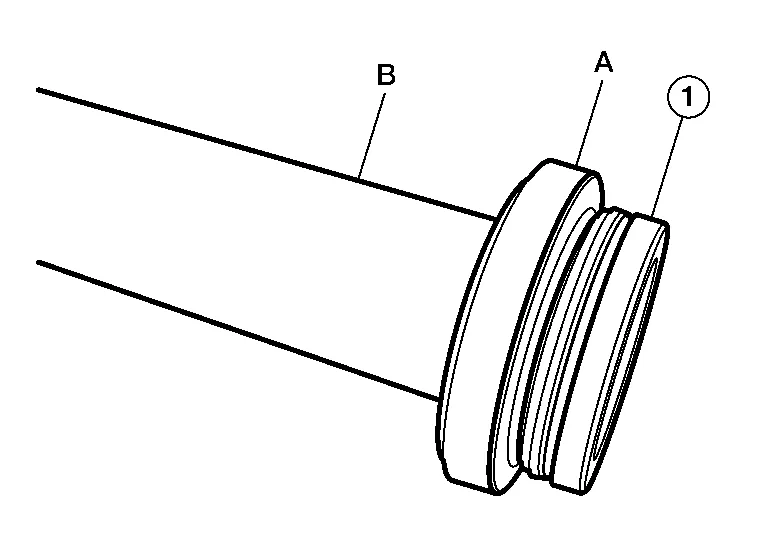
| Tool (A) | : — (J-52390) |
| Tool (B) | : — (J-8092) |
| Dimension (A) | : 2.0 - 2.6 mm (0.079 - 0.102 in) |
CAUTION:
Do not reuse transfer cover oil seal.
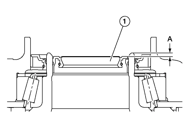
Verify the transfer cover oil seal (2) is installed to the correct depth (A).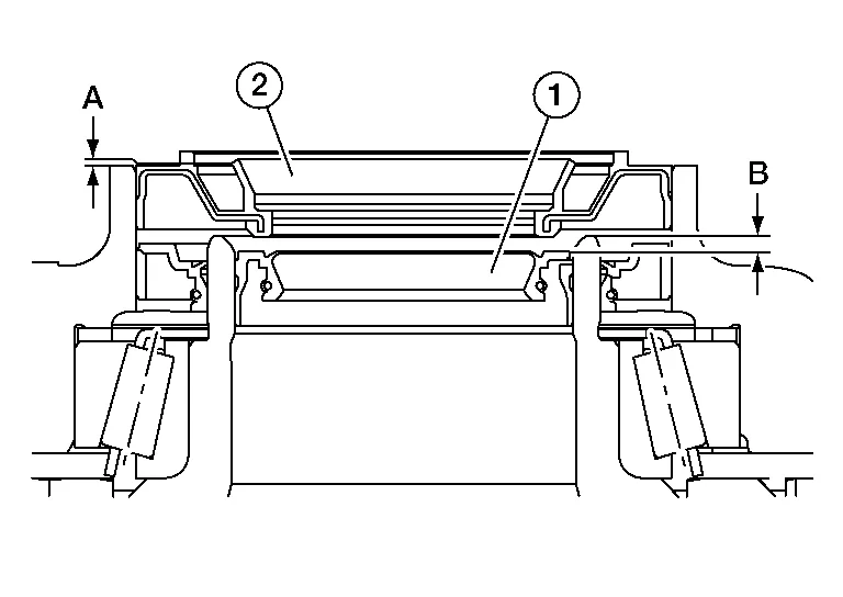
| Dimension (A) | : 0.0 - 0.6 mm (0.000 - 0.024 in) |
| (1) | : Drive shaft oil seal |
| (B) | : Drive shaft oil seal installation depth |
Install the support bearing bracket.
-
Tighten the support bearing bracket bolts in numerical order as shown.
-
Refer to the following for installation positions of the bolts:
| M10 bolt | No. 1 - 4: | 48.0 N·m (4.9 kg-m, 35 ft-lb) |
| : Front |
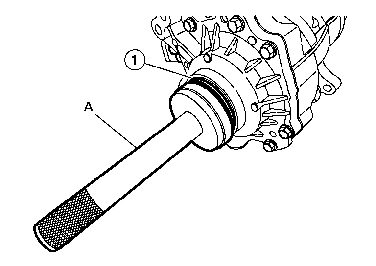
In order to prevent damage to the transfer cover oil seal, place Tool (A) onto the applicable oil seal before inserting the drive shaft as shown. Slide the drive shaft into the slide joint and tap with a hammer to install securely.
| Tool (A) | : KV38107900 (J-52469–1) |
Install the bearing retainer.
-
Tighten the bearing retainer bolts in the numerical order shown.
| M8 bolt | No. 1 and No. 2: | 25.0 N·m (2.6 kg-m, 18 ft-lb) |
| : Front |
Pull the joint sub-assembly in the axial direction away from the transfer assembly. Confirm the joint sub-assembly cannot be pulled out.
Clean the matching surfaces of the wheel hub lock nut and the wheel hub and bearing.
CAUTION:
Do not apply lubricating oil to these surfaces.
Tighten the wheel hub lock nut to specification. Refer to Exploded View (RH).
CAUTION:
-
Do not reuse the wheel hub lock nut.
-
Do not use power tools to tighten the wheel hub lock nut.
When installing the cotter pin (1) and the nut retainer (2), securely bend the cotter pin to prevent rattles.

CAUTION:
Do not reuse the cotter pin.
Install the studs in the exhaust manifold (if removed), and tighten to specification.
| Exhaust manifold studs | : 15.4 N·m (1.6 kg-m, 11 ft-lb) |
Install the exhaust manifold gasket in the direction shown.
CAUTION:
Do not reuse exhaust manifold gasket.
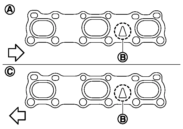
| (A) | : Bank 1 |
| (B) | : Triangle press |
| (C) | : Bank 2 |
| : Engine front |
Install the exhaust manifold (bank 1) nuts and tighten to specification in the order shown.
| : Engine front |
NOTE:
Number 7 and 8 are tightened a second time.
CAUTION:
-
Before installing a heated oxygen sensor or air fuel ratio (A/F) sensor, clean the exhaust manifold threads using Tool and apply anti-seize lubricant.
Tool number : — (J-43897-18) -
Do not over-tighten the air fuel ratio (A/F) sensor or heated oxygen sensors. Doing so may cause damage.
Tool numbers : KV10114400 (J-38365) : KV991J0050 (J-44626)
Installation of remaining components is in the reverse order of removal.
 Drive Shaft Oil Seal
Exploded View
1.
Transfer case assembly
2.
Drive shaft oil seal
3.
Transfer cover oil seal
Removal and Installation
REMOVALRemove the front drive shaft (RH)...

Other information:
Nissan Murano (Z52) 2015-2024 Service Manual: Parking Brake System :: Precaution. Precautions
Precaution for Supplemental Restraint System (SRS) "AIR BAG" and "SEAT BELT PRE-TENSIONER" The Supplemental Restraint System such as “AIR BAG” and “SEAT BELT PRE-TENSIONER”, used along with a front seat belt, helps to reduce the risk or severity of injury to the driver and front passenger for certain types of collisions...
Nissan Murano (Z52) 2015-2024 Service Manual: P2096 A/f Sensor 1
DTC Description DTC DETECTION LOGIC DTC CONSULT screen terms (Trouble diagnosis content) DTC detection condition P2096 POST CAT FUEL TRIM SYS B1 (Post catalyst fuel trim system too lean bank 1) Diagnosis condition — Signal (terminal) — Threshold The output voltage computed by ECM from the A/F sensor 1 signal is shifts to the lean side for a specified period Diagnosis delay time — P2097 POST CAT FUEL TRIM SYS B1 (Post catalyst fuel trim system too rich bank 1) Diagnosis condition — Signal (terminal) — Threshold The A/F signal computed by ECM from the A/F sensor 1 signal is shifts to the rich side for a specified period Diagnosis delay time — P2098 POST CAT FUEL TRIM SYS B2 (Post catalyst fuel trim system too lean bank 2) Diagnosis condition — Signal (terminal) — Threshold The output voltage computed by ECM from the A/F sensor 1 signal is shifts to the lean side for a specified period Diagnosis delay time — P2099 POST CAT FUEL TRIM SYS B2 (Post catalyst fuel trim system too rich bank 2) Diagnosis condition — Signal (terminal) — Threshold The A/F signal computed by ECM from the A/F sensor 1 signal is shifts to the rich side for a specified period Diagnosis delay time — POSSIBLE CAUSEDTC P2096 A/F sensor 1 (bank 1) A/F sensor 1 heater Heated oxygen sensor 2 (bank 1) Fuel pressure Fuel injector Intake air leaks Exhaust gas leaks DTC P2097 A/F sensor 1 (bank 1) A/F sensor 1 heater Heated oxygen sensor 2 (bank 1) Fuel pressure Fuel injector Intake air leaks Exhaust gas leaks DTC P2098 A/F sensor 1 (bank 2) A/F sensor 1 heater Heated oxygen sensor 2 (bank 2) Fuel pressure Fuel injector Intake air leaks Exhaust gas leaks DTC P2099 A/F sensor 1 (bank 2) A/F sensor 1 heater Heated oxygen sensor 2 (bank 2) Fuel pressure Fuel injector Intake air leaks Exhaust gas leaks FAIL-SAFENot applicable DTC Confirmation Procedure PRECONDITIONING If DTC Confirmation Procedure has been previously conducted, always perform the following before conducting the next test...
Categories
- Manuals Home
- Nissan Murano Owners Manual
- Nissan Murano Service Manual
- Turning the AEB system on/off
- Memory storage function (key-link)
- All-Wheel Drive (AWD) (if so equipped)
- New on site
- Most important about car
Autolight system
The autolight system allows the headlights to turn on and off automatically. The autolight system can:
Turn on the headlights, front parking, tail, license plate and instrument panel lights automatically when it is dark. Turn off all the lights (except daylight running lights) when it is light. Keep all the lights on for a period of time after you place the ignition switch in the OFF position and all doors are closed.