
Nissan Murano: Power Supply, Ground & Circuit Elements :: System Description / System. Power Supply, Ground & Circuit Elements
For example, when current is 30A, the circuit is broken within 8 to 20 seconds.
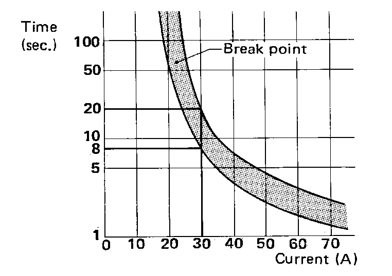
This circuit breaker is used for the following systems:
-
Power windows
-
Power moonroof
-
Power seat
-
Power lumbar
-
Power sunshade
The PTC thermistor generates heat in response to current flow. The temperature (and resistance) of the thermistor element varies with current flow. Excessive current flow will cause the element's temperature to rise. When the temperature reaches a specified level, the electrical resistance will rise sharply to control the circuit current.
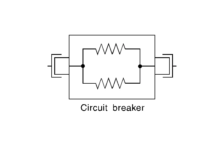
Reduced current flow will cause the element to cool. Resistance falls accordingly and normal circuit current flow is allowed to resume.
HARNESS CONNECTOR (TAB-LOCKING TYPE)
-
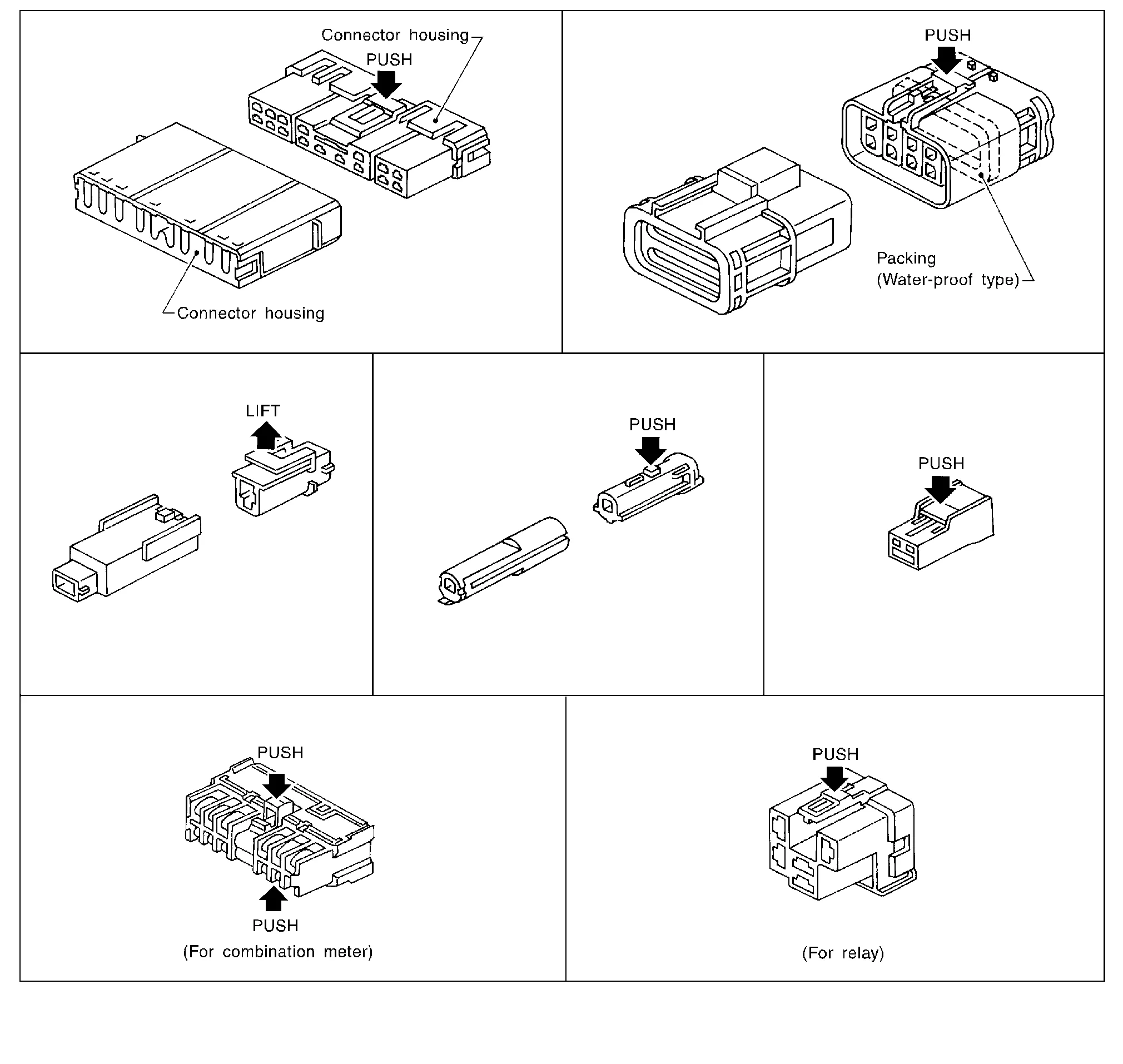
The tab-locking type connectors help prevent accidental looseness or disconnection.
-
The tab-locking type connectors are disconnected by pushing or lifting the locking tab(s). Refer to the figure below.
Refer to the next page for description of the slide-locking type connector.
CAUTION:
Do not pull the harness or wires when disconnecting the connector.
[Example]
HARNESS CONNECTOR (SLIDE-LOCKING TYPE)
-
A new style slide-locking type connector is used on certain systems and components, especially those related to OBD.
-
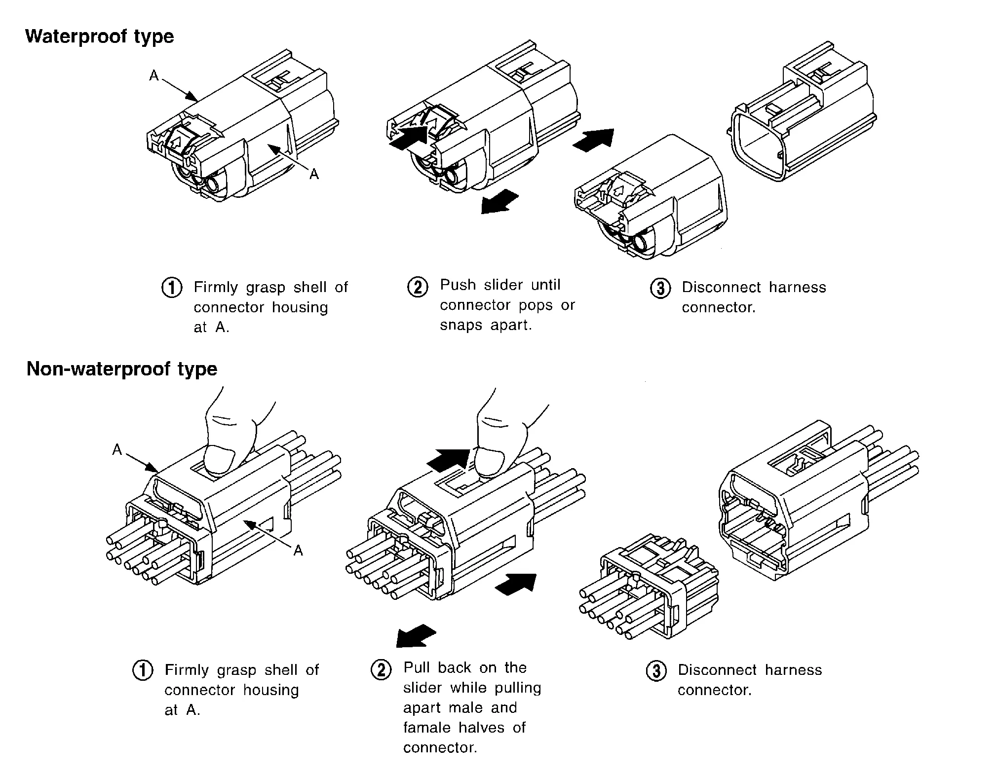
The slide-locking type connectors help prevent incomplete locking and accidental looseness or disconnection.
-
The slide-locking type connectors are disconnected by pushing or pulling the slider. Refer to the figure below.
CAUTION:
-
Do not pull the harness or wires when disconnecting the connector.
-
Be careful not to damage the connector support bracket when disconnecting the connector.
[Example]
HARNESS CONNECTOR (LEVER LOCKING TYPE)
-
Lever locking type harness connectors are used on certain control units and control modules such as ECM, ABS actuator and electric unit (control unit), etc.
-
Lever locking type harness connectors are also used on super multiple junction (SMJ) connectors.
-
Always confirm the lever is fully locked in place by moving the lever as far as it will go to ensure full connection.
CAUTION:
-
Always confirm the lever is fully released (loosened) before attempting to disconnect or connect these connectors to avoid damage to the connector housing or terminals.
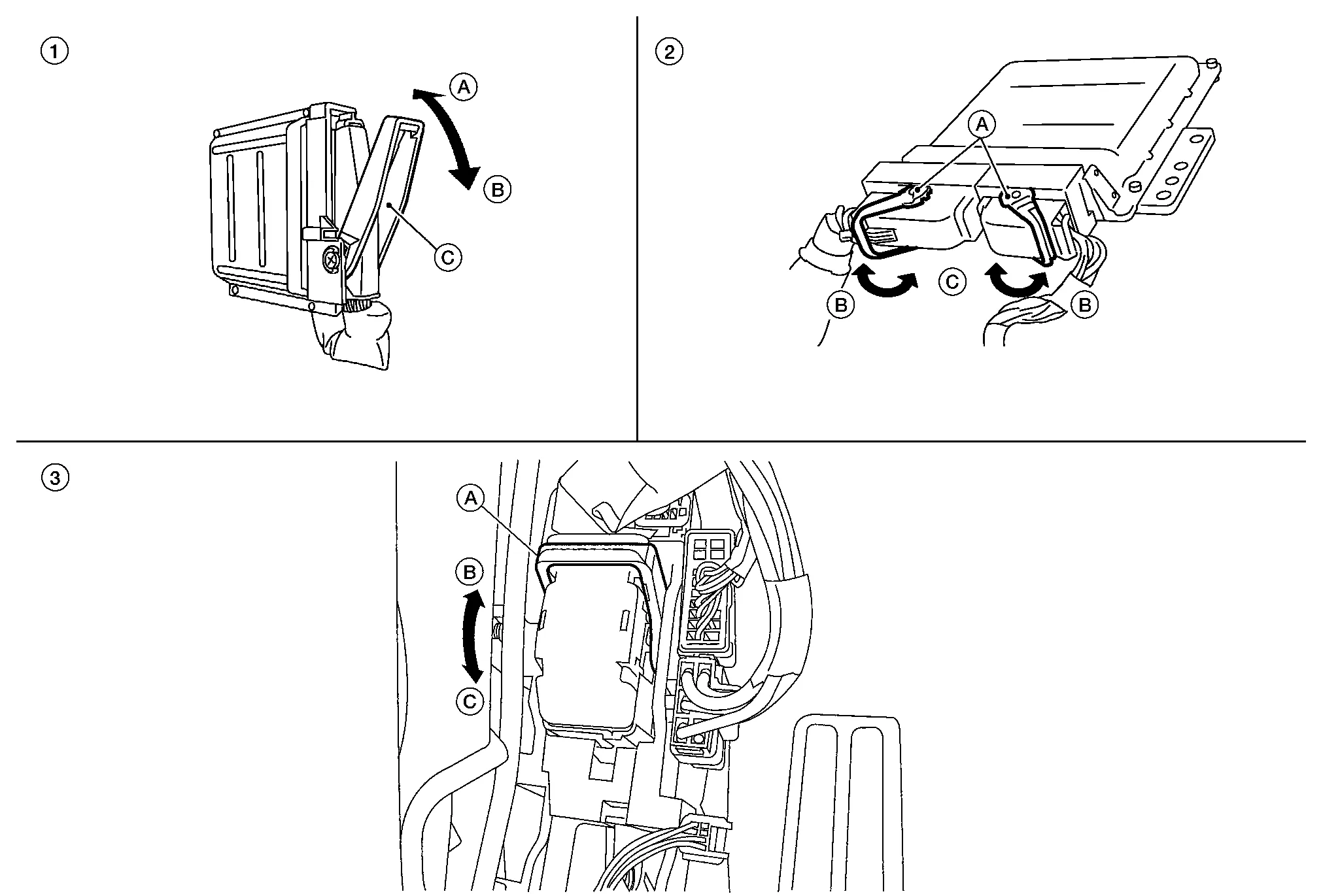
| 1. | Control unit with single lever | 2. | Control unit with dual lever | 3. | SMJ connector |
| A. Fasten | A. Lever | A. Lever | |||
| B. Loosen | B. Fasten | B. Fasten | |||
| C. Lever | C. Loosen | C. Loosen |
HARNESS CONNECTOR (DIRECT-CONNECT SRS COMPONENT TYPE)
-
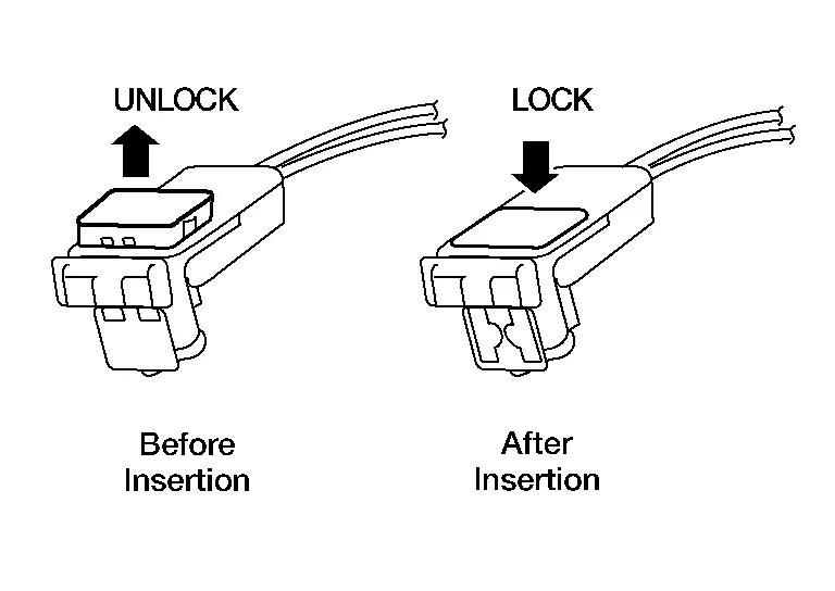
SRS direct-connect type harness connectors are used on certain SRS components such as air bag modules and seat belt pre-tensioners.
-
Always pull up to release black locking tab prior to removing connector from SRS components.
-
Always push down to lock black locking tab after installing connector to SRS components. When locked, the black locking tab is level with the connector housing.
CAUTION:
-
Do not pull the harness or wires when removing connectors from SRS components.
HARNESS CONNECTOR (SLIDE DOUBLE LOCKING SRS COMPONENT TYPE)
-
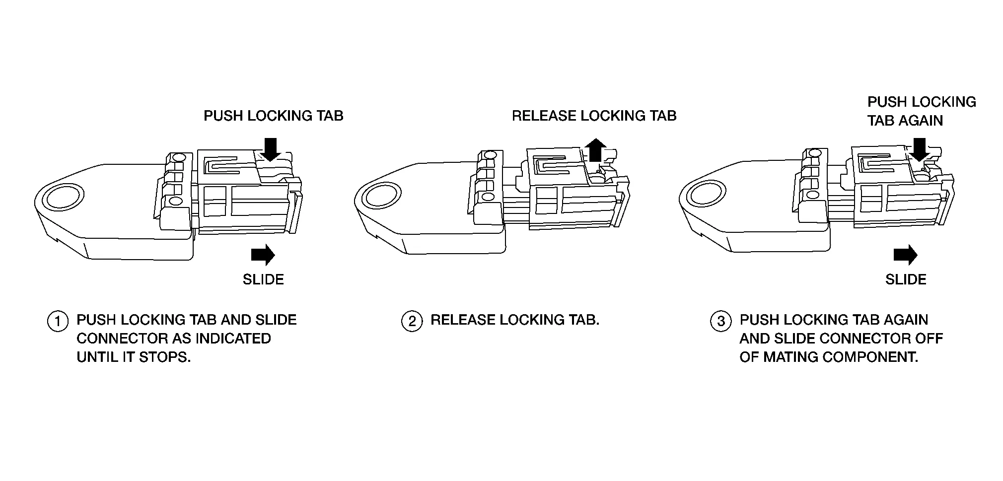
A new style slide double locking type connector is used on certain systems and components, especially those related to airbag control systems.
-
The slide double locking type connectors help prevent incomplete locking and accidental looseness or disconnection.
-
The slide double locking type connectors are disconnected by pushing or pulling the slider. Refer to the figure below.
CAUTION:
-
Do not pull the harness or wires when disconnecting the connector.
NORMAL OPEN, NORMAL CLOSED AND MIXED TYPE RELAYS
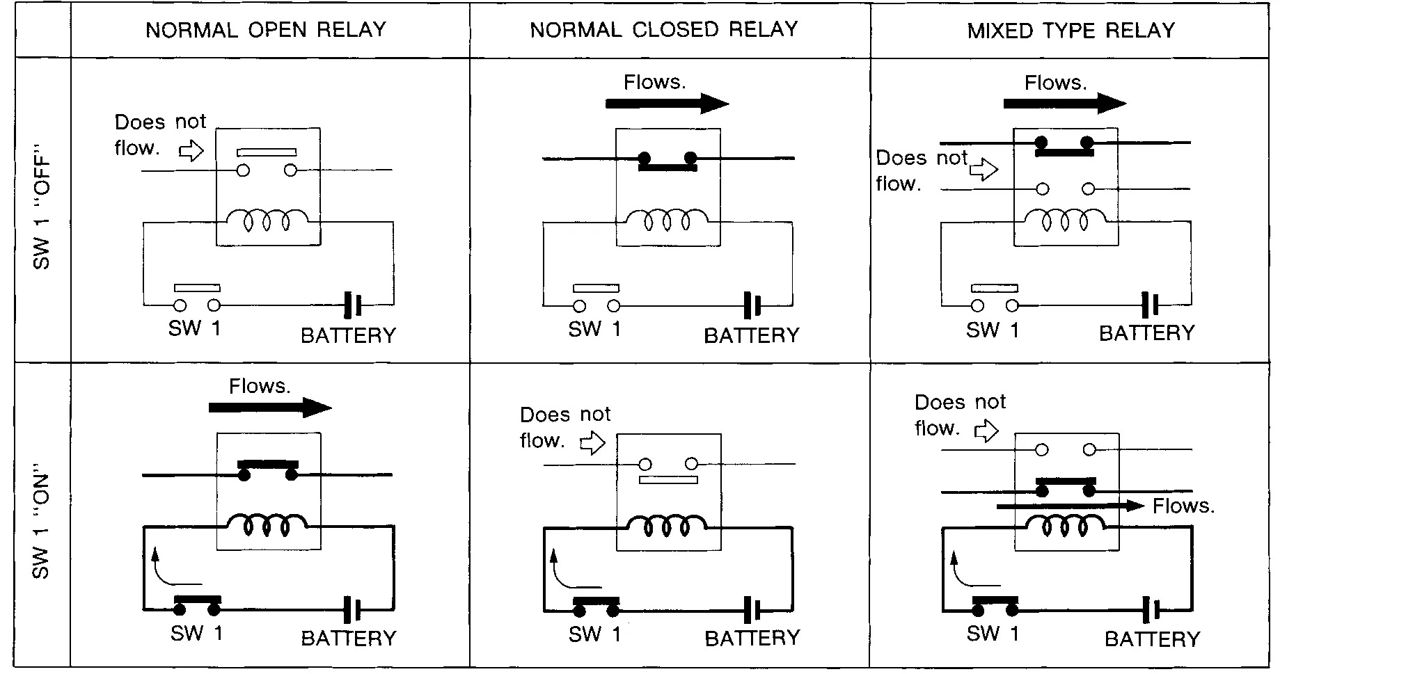
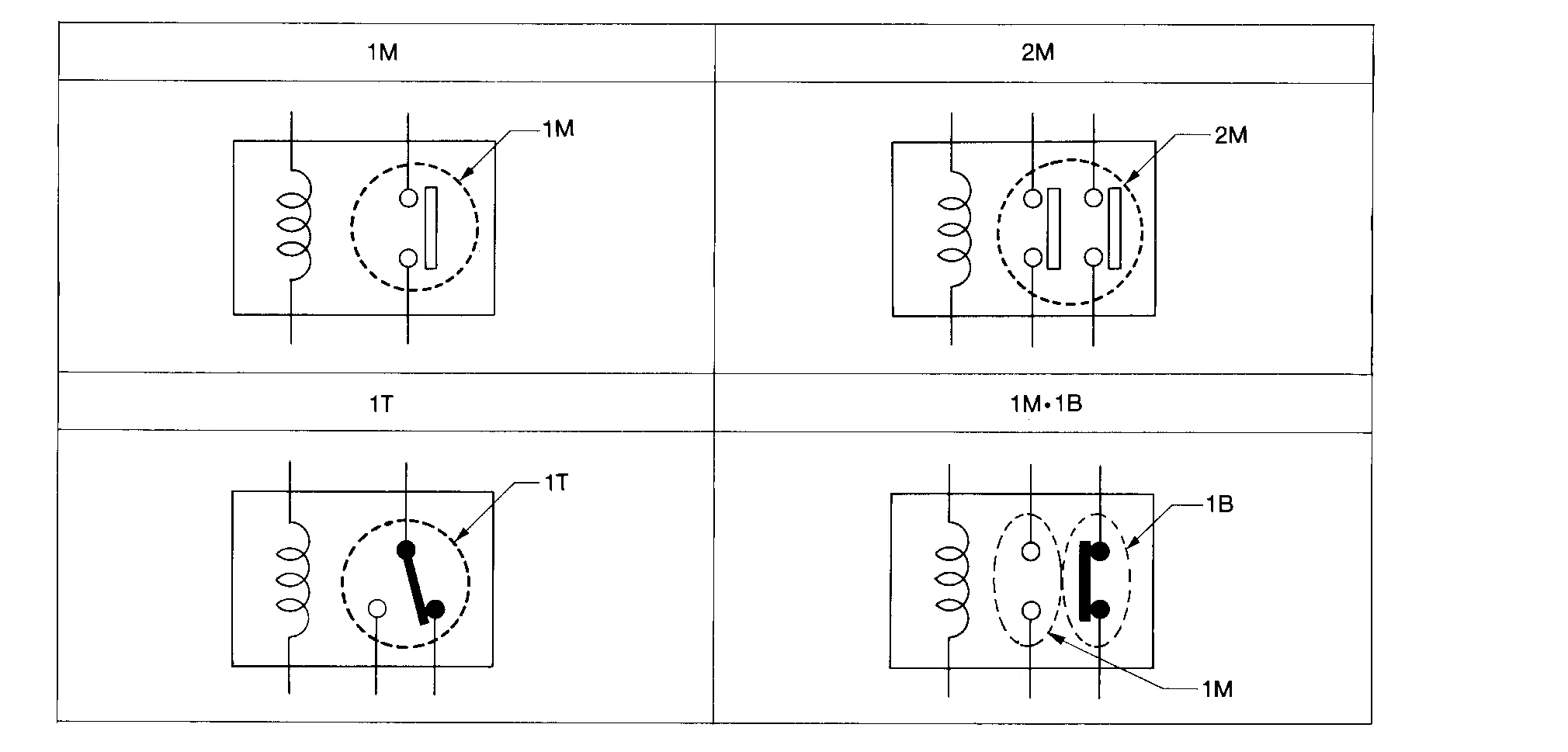
Relays can mainly be divided into three types: normal open, normal closed and mixed type relays.
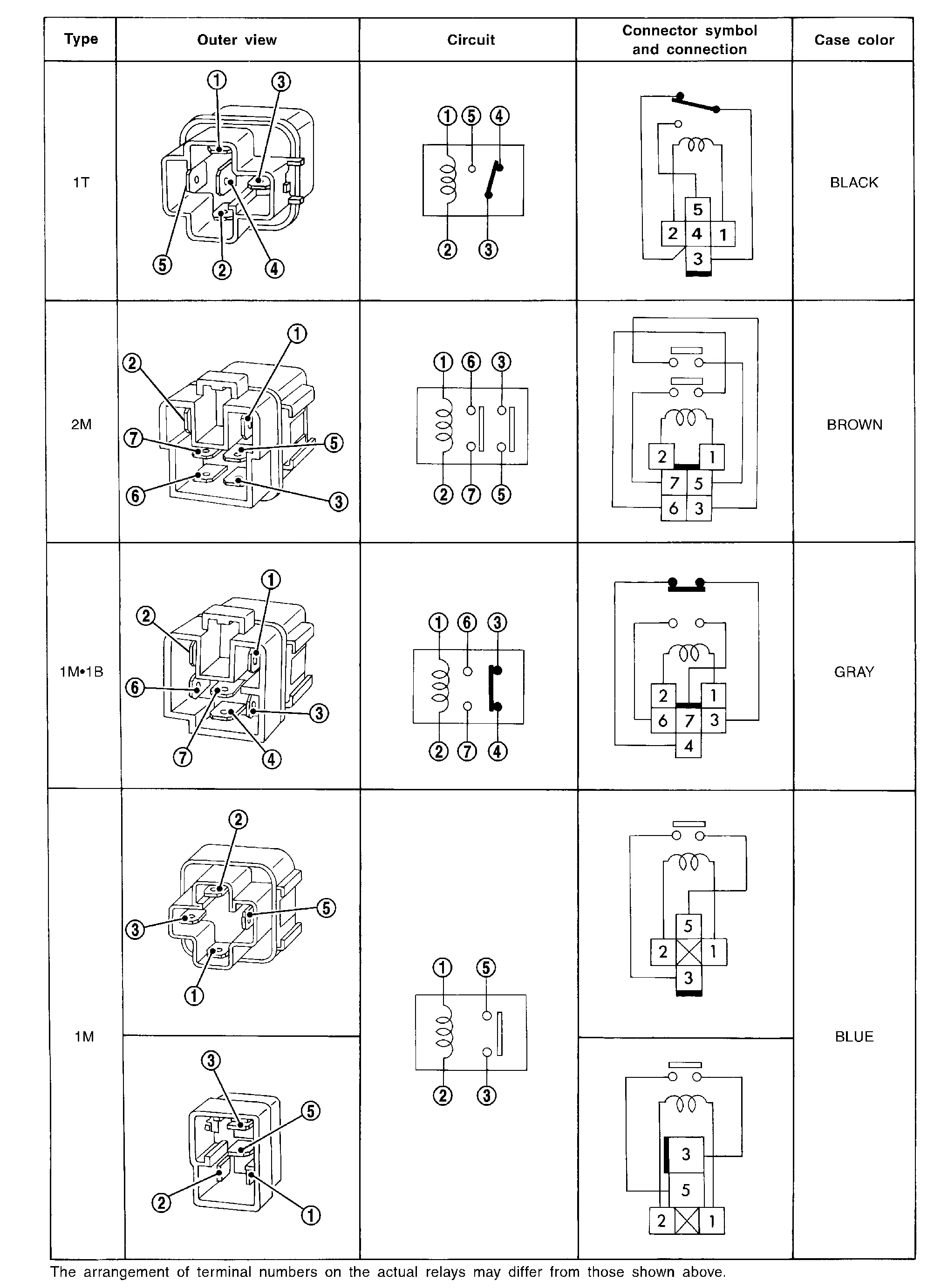
TYPE OF STANDARDIZED RELAYS
| 1M ···················· 1 Make | 2M ···················· 2 Make |
| 1T ···················· 1 Transfer | 1M·1B ···················· 1 Make 1 Break |
 Component Parts. Electrical Units Location
Component Parts Location
No. Component
1.
Battery
2.
Fusible Link Box (Battery)
3.
Fuse, Fusible link, and Relay box
4.
IPDM E/R (Intelligent Power Distribution Module Engine Room)
5...

Other information:
Nissan Murano (Z52) 2015-2024 Service Manual: Starting System :: Precaution. Precautions
Precaution for Supplemental Restraint System (SRS) "AIR BAG" and "SEAT BELT PRE-TENSIONER" The Supplemental Restraint System such as “AIR BAG” and “SEAT BELT PRE-TENSIONER”, used along with a front seat belt, helps to reduce the risk or severity of injury to the driver and front passenger for certain types of collisions...
Nissan Murano (Z52) 2015-2024 Service Manual: Back-Up Lamp Circuit
Component Function Check CHECK BACK-UP LAMP OPERATION Start the engine. With operating the CVT shift selector, check that the back-up lamp is turned ON. CVT shift selector position: Reverse : Back-up lamp ON CVT shift selector position: Other than above : Back-up lamp OFF Is the inspection result normal? YES>> Back-up lamp circuit is normal...
Categories
- Manuals Home
- Nissan Murano Owners Manual
- Nissan Murano Service Manual
- Rear bench seat adjustment
- Settings
- All-Wheel Drive (AWD) (if so equipped)
- New on site
- Most important about car
