Nissan Murano: System Description / System
SYSTEM DIAGRAM
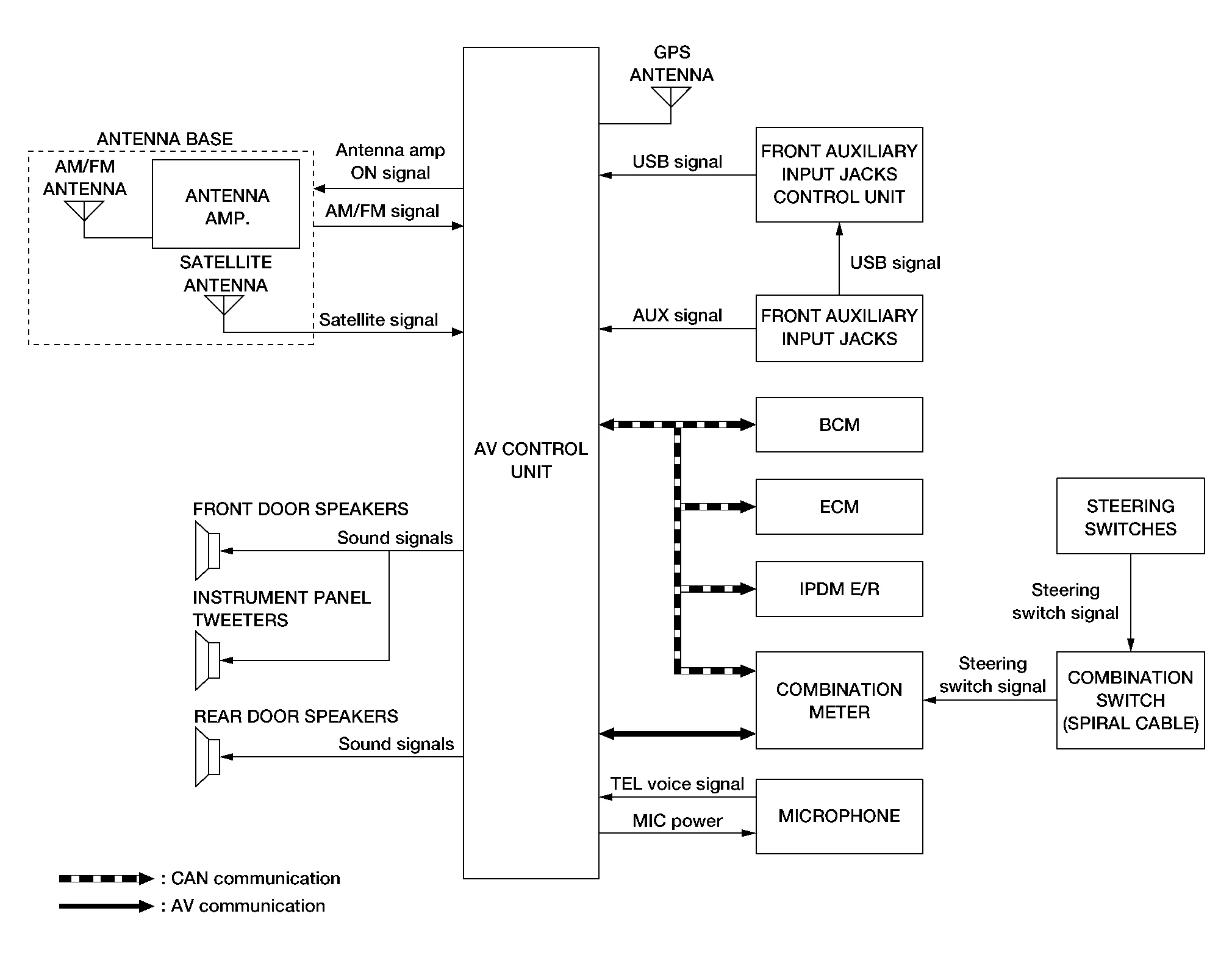
AV Control Unit Input Signal (AV Communication)
| Transmit unit | Signal name |
|---|---|
| Combination meter | Steering switch signal |
AV Control Unit Input Signal (CAN Communication)
| Transmit unit | Signal name |
|---|---|
| BCM | Door switches state signal |
| Combination meter |
|
| ECM | Engine RPM Signal |
| IPDM E/R | Battery voltage signal |
AUDIO SYSTEM
The audio system consists of the following components:
-
AV control unit
-
Instrument panel tweeters
-
Front door speakers
-
Rear door speakers
-
Front auxiliary input jacks
-
Front auxiliary input jacks control unit
-
Microphone
-
Steering switches
-
Combination meter
-
Combination switch (spiral cable)
-
Accessory relay-2
-
Antenna base (AM/FM antenna, antenna amp. and satellite antenna)
When the audio system is on:
-
AM/FM signals received by the AM/FM antenna are amplified by the antenna amp. and sent to the AV control unit. The AV control unit then sends audio signals to the speakers.
-
Satellite signals received by the satellite antenna are sent to the AV control unit. The AV control unit then sends audio signals to the speakers.
Refer to Owner's Manual for audio system operating instructions.
NAVIGATION SYSTEM
Description
-
The navigation system can be operated by control panel of the AV control unit and display (touch panel) of the AV control unit.
-
Guide sound during the operation of the navigation system is output from AV control unit to front tweeters.
-
AV control unit calculates the Nissan Murano vehicle location based on the signals from GYRO (angle speed sensor), vehicle sensor, and GPS satellite, as well as the map data from map SD-card. The Nissan Murano vehicle location is displayed on the AV control unit.
POSITION DETECTION PRINCIPLE
The navigation system periodically calculates the vehicle's current position according to the following three signals:
-
Travel distance of the vehicle as determined by the vehicle speed sensor
-
Turning angle of the Nissan Murano vehicle as determined by the gyroscope (angular velocity sensor)
-
Direction of vehicle travel as determined by the GPS antenna (GPS information)
The current position of the vehicle is then identified by comparing the calculated vehicle position with map data read from the map SD-card (map-matching), and indicated on the screen as a Nissan Murano vehicle mark. More accurate data is judged and used by comparing vehicle position detection results found by the GPS with the result by map-matching.
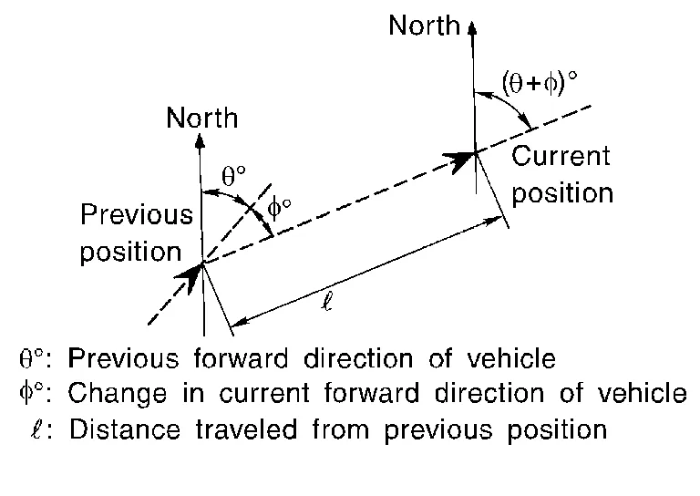
The current vehicle position will be calculated by detecting the distance the vehicle moved from the previous calculation point and its direction.
-
Travel distance
Travel distance calculations are based on the vehicle speed sensor input signal. Therefore, the calculation may become incorrect as the tires wear down. To prevent this, an automatic distance correction function has been adopted.
-
Travel direction
Change in the travel direction of the Nissan Murano vehicle is calculated by a gyroscope (angular velocity sensor) and a GPS antenna (GPS information). They have both advantages and disadvantages.
Type Advantage Disadvantage Gyroscope
(angular velocity sensor)Can detect the Nissan Murano vehicle's turning angle quite accurately. Direction errors may accumulate when Nissan Murano vehicle is driven for long distances without stopping. GPS antenna
(GPS information)Can detect the Nissan Murano vehicle's travel direction (North/South/East/West). Correct direction cannot be detected when Nissan Murano vehicle speed is low. More accurate traveling direction is detected because priorities are set for the signals from these two devices according to the situation.
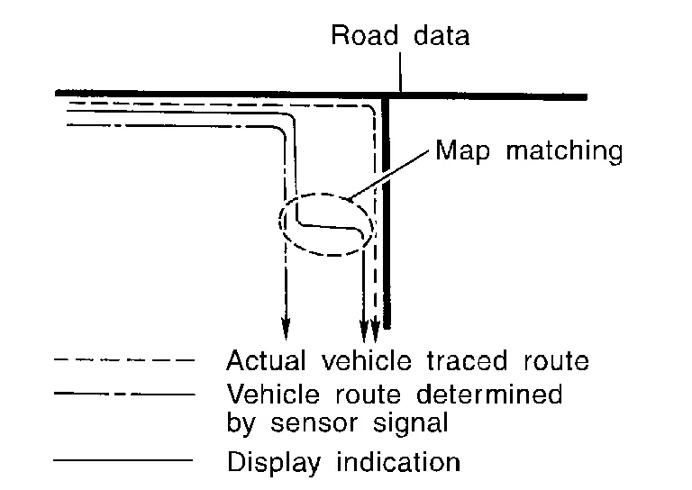
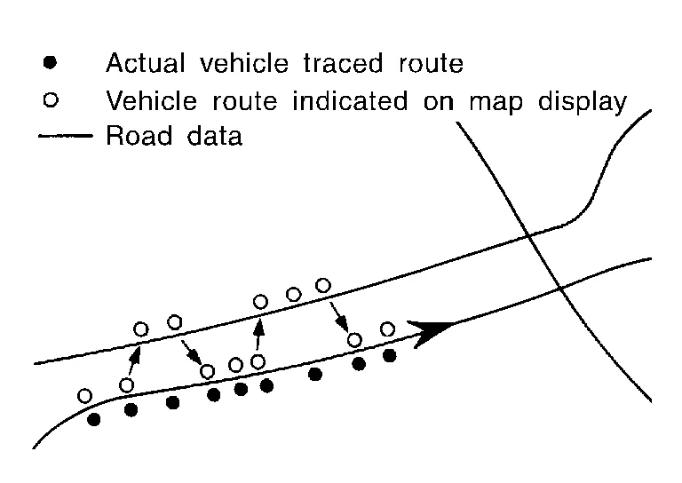
MAP-MATCHING
Map-matching compares a current location detected by the method in the “Location Detection Principle” with a road map data from map SD-card.
 NOTE:
NOTE:
The road map data is based on data stored in the map SD-card.
The vehicle position may not be corrected under the following circumstances and after driving for a certain time when GPS information is difficult to receive. In this case, the Nissan Murano vehicle mark on the display must be corrected manually:
-
In map-matching, alternative routes to reach the destination will be shown and prioritized, after the road on which the Nissan Murano vehicle is currently driven has been judged and the vehicle mark has been repositioned.
Alternative routes will be shown in different order of priority, and the incorrect road can be avoided if there is an error in distance and/or direction.
Routes are of the same priority if two roads are running in parallel. Therefore, the Nissan Murano vehicle mark may appear on either of them alternately, depending on maneuvering of the steering wheel and configuration of the road.
-
Map-matching does not function correctly when a road on which the Nissan Murano vehicle is driving is new and not recorded in the map SD-card, or when road pattern stored in the map data and the actual road pattern are different due to repair.
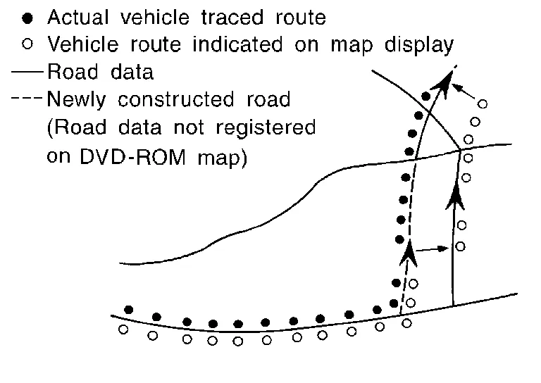
The map-matching function may find another road and position the Nissan Murano vehicle mark on it when driving on a road not present in the map. Then, the vehicle mark may change to it when the correct road is detected.
-
Effective range for comparing the Nissan Murano vehicle position and travel direction calculated by the distance and direction with the road data read from the map SD-card is limited. Therefore, correction by map-matching is not possible when there is an excessive gap between current Nissan Murano vehicle position and the position on the map.
GPS (Global Positioning System)
GPS (Global Positioning System) is developed for and is controlled by the US Department of Defense. The system utilizes GPS satellites (NAVSTAR), transmitting out radio waves while flying on an orbit around the earth at an altitude of approximately 21,000 km (13,049 mile).
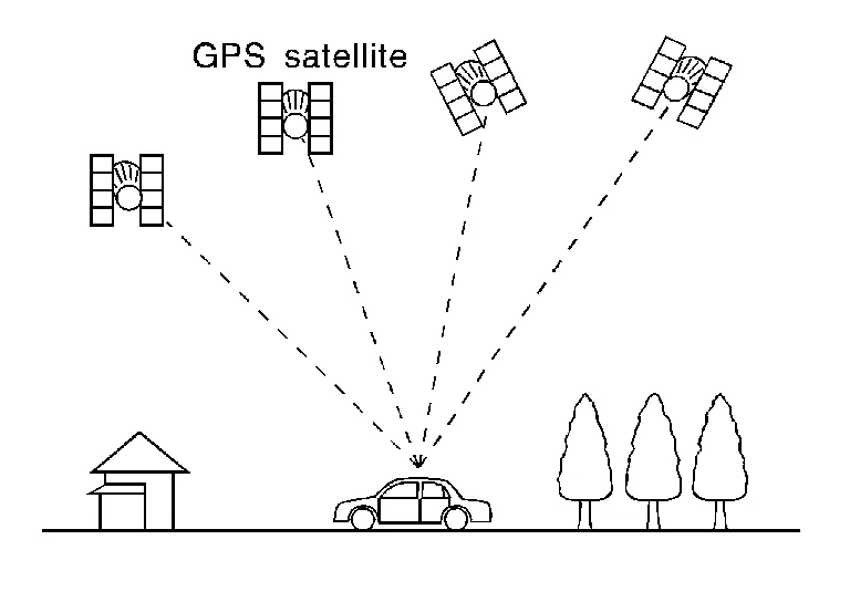
The receiver calculates the travel position in three dimensions (latitude/longitude/altitude) according to the time lag of the radio waves that four or more GPS satellites transmit (three-dimensional positioning). The GPS receiver calculates the travel position in two dimensions (latitude/longitude) with the previous altitude data if the GPS receiver receives only three radio waves (two-dimensional positioning). GPS position correction is not performed while stopping the Nissan Murano vehicle.
Accuracy of the GPS will deteriorate under the following conditions:
-
In two-dimensional positioning, GPS accuracy will deteriorate when altitude of the vehicle position changes.
-
The position of GPS satellite affects GPS detection precision. The position detection may not be precisely performed.
-
The position detection is not performed if GPS receiver does not receive radio waves from GPS satellites. (Inside a tunnel, parking in a building, under an elevated highway etc.) GPS receiver may not receive radio waves from GPS satellites if any object is placed on the GPS antenna.
NOTE:
-
The detection result has an error of approximately 10 m (32.81 ft) even with a high-precision three dimensional positioning.
-
There may be cases when the accuracy is lowered and radio waves are stopped intentionally because the GPS satellite signal is controlled by the US trace control center.
HANDS-FREE PHONE SYSTEM
System Operation
NOTE:
Cellular telephones must have their wireless connection set up (paired) before using the Bluetooth® telephone system.
The Bluetooth® telephone system allows users who have a Bluetooth® cellular telephone to make a wireless connection between their cellular telephone and the AV control unit. Hands-free cellular telephone calls can be sent and received. Some Bluetooth® cellular telephones may not be recognized by the AV control unit. When a cellular telephone or the AV control unit is replaced, the telephone must be paired with the AV control unit. Different cellular telephones may have different pairing procedures, refer to the cellular telephone operating manual.
Refer to the Owner's Manual for Bluetooth® telephone system operating instructions.
AV control unit
When the ignition switch is turned ON, the AV control unit will power up. During power up, the AV control unit is initialized and performs various self-checks. Initialization may take up to 20 seconds.
Steering Switches
When buttons on the steering switches are pushed, the resistance in steering switch circuits change, depending on which button is pushed.
The following functions can be performed using the steering switches:
-
Initiate self-diagnosis of the Bluetooth® telephone system
-
Start a voice recognition session
-
Answer and end telephone calls
-
Adjust the volume of calls
-
Record memos
Microphone
The microphone is located in the roof in the map lamp assembly. The microphone sends a signal to the AV control unit.
SATELLITE RADIO FUNCTION
-
Satellite radio function is built into AV control unit.
-
Sound signal (satellite radio) is received by satellite antenna and transmitted to AV control unit. AV control unit outputs sound signal to each speaker.
FRONT AUXILIARY INPUT JACKS FUNCTION
-
Sound and data signals are transmitted from USB interfaces to the front auxiliary input jacks control unit, then the AV control unit and output to each speaker.
-
Sound signals are transmitted from AUX jack to the AV control unit and output to each speaker.
SPEED SENSITIVE VOLUME SYSTEM
-
Volume level of this system goes up and down automatically in proportion to the vehicle speed.
-
The control level can be selected by the customer.
 Component Parts. Navigation Without Bose
Component Parts Location
No. Component Function
1.
Rear door speaker RH
Refer to Speakers.
2.
Microphone
Refer to Microphone.
3.
Front door speaker RH
Refer to Speakers...
 Diagnosis System (av Control Unit)
Description
The AV control unit on board diagnosis performs the following functions listed in the table below: Mode Description
Self Diagnosis
Multi AV system diagnosis...
Other information:
Nissan Murano (Z52) 2015-2024 Service Manual: Recommended Fluids and Lubricants
Fluids and Lubricants The following are approximate capacities, The actual refill capacities may be slightly different.When refilling, follow the procedures described elsewhere in this manual. Fluid type Capacity (approximate) Recommended Fluids/Lubricants Metric Measure US Measure Imperial Measure Fuel 71...
Nissan Murano (Z52) 2015-2024 Service Manual: Check Anti-Pinch Function
Description The initialization is necessary for normal operation of power window system If any of the following operations are performed: When control unit is replaced. Electric power supply to power window switch or motor is interrupted by blown fuse or disconnection and connection of the negative battery terminal...
Categories
- Manuals Home
- Nissan Murano Owners Manual
- Nissan Murano Service Manual
- Passenger compartment
- System malfunction
- Rear bench seat adjustment
- New on site
- Most important about car
LATCH (Lower Anchors and Tethers for CHildren) system

LATCH system lower anchor locations - bench seat
Your vehicle is equipped with special anchor points that are used with LATCH system compatible child restraints. This system may also be referred to as the ISOFIX or ISOFIX compatible system. With this system, you do not have to use a vehicle seat belt to secure the child restraint unless the combined weight of the child and child restraint exceeds 65 lbs. (29.5 kg). If the combined weight of the child and child restraint is greater than 65 lbs. (29.5 kg), use the vehicle’s seat belt (not the lower anchors) to install the child restraint. Be sure to follow the child restraint manufacturer’s instructions for installation.