
Nissan Murano: Brake Control System :: Automatic Emergency Braking / Symptom Diagnosis
Nissan Murano (Z52) 2015-2024 Service Manual / Brakes / Brake Control System :: Automatic Emergency Braking / Symptom Diagnosis
- Automatic Emergency Braking System Symptoms
- System Settings Cannot Be Turned On/off on the Integral Switch
- Aeb Warning Lamp Is Blinking
 Dtc/circuit Diagnosis. Automatic Emergency Braking
Diagnosis Procedure
AUTOMATIC EMERGENCY BRAKE DIAGNOSIS
The system will be cancelled automatically with a beep sound and AEB warning lamp on the combination meter will illuminate, when the system will not operate properly...
 Automatic Emergency Braking System Symptoms
Symptom Table
Before performing diagnosis, check that it is not a symptom caused by normal operation. Refer to System Description. Symptom Confirmation item Inspection item/Reference page
AEB system display does not illuminate
All of system display does not illuminate
System settings cannot be turned ON/OFF
Refer to Diagnosis Procedure
Other information display is not illuminated
Combination meter
Refer to DTC Index
AEB warning lamp does not illuminate
All of system display does not illuminate
System settings cannot be turned ON/OFF
Refer to Diagnosis Procedure
Other information display is not illuminated
Combination meter
Refer to DTC Index
AEB warning buzzer is not sounding (Warning display is functioning normally)
—
Chime does not sound...
Other information:
Nissan Murano (Z52) 2015-2024 Service Manual: Mode Door Motor
Diagnosis Procedure CHECK MODE DOOR MOTOR POWER SUPPLY Ignition switch ON. Check voltage between mode door motor harness connector and ground. + − Voltage (Approx.) Mode door motor Connector Terminal M154 1 Ground Battery voltage Is the inspection result normal? YES>> GO TO 2...
Nissan Murano (Z52) 2015-2024 Service Manual: Motion Activated Back Door Does Not Operate Properly
Diagnosis Procedure Automatic back door open/close function does not operate properly when using motion activated back door sensor.CHECK BATTERY Check the vehicle battery condition. Refer to Work Flow. Is the battery in good condition? YES>> GO TO 2...
Categories
- Manuals Home
- Nissan Murano Owners Manual
- Nissan Murano Service Manual
- All-Wheel Drive (AWD) (if so equipped)
- Jacking up vehicle and removing the damaged tire
- Turning the AEB system on/off
- New on site
- Most important about car
Vehicle security system
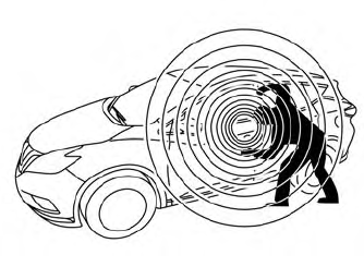
Your vehicle has two types of security systems:
Vehicle security system NISSAN Vehicle Immobilizer SystemThe vehicle security system provides visual and audible alarm signals if someone opens the doors, liftgate or the hood when the system is armed. It is not, however, a motion detection type system that activates when a vehicle is moved or when a vibration occurs.

Copyright © 2026 www.nimurano.com