Nissan Murano: Steering / Steering System :: Unit Removal and Installation. Steering Gear and Linkage
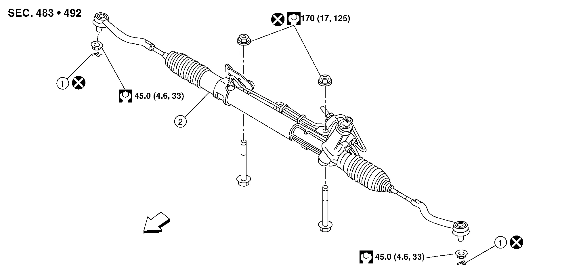
| 1. | Cotter pin | 2. | Steering gear | Front |
 NOTE:
NOTE:
When removing components such as hoses, tubes/lines, etc., cap or plug openings to prevent fluid from spilling.
REMOVAL
Set the front wheels and tires to the straight-ahead position.
Remove the front wheels and tires using power tool. Refer to Exploded View.
Drain the power steering fluid. Refer to Draining and Refilling.
Remove the cotter pins from outer sockets (RH/LH).
Loosen the outer socket nuts and separate outer sockets from the steering knuckles (RH/LH) using suitable tool.
CAUTION:
Leave the outer socket nuts half threaded on the outer socket to prevent damage to threads and to prevent the suitable tool from coming off suddenly.
Remove outer socket nuts and separate the outer sockets from the steering knuckles (RH/LH).
Remove the rear engine bracket. Refer to Exploded View.
Remove the front exhaust tube. Refer to Exploded View.
Remove steering gear heat shield.
Remove bolt (A) and separate the steering intermediate shaft (1) from the steering gear (2).

CAUTION:
With the steering linkage disconnected, the spiral cable may snap by turning the steering wheel beyond the limited number of turns. Secure the steering wheel during removal of the steering gear.
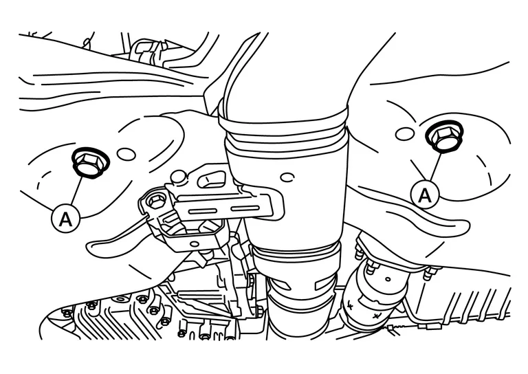
Remove the steering gear nuts and bolts (A). Position the steering gear forward.
Remove the front stabilizer. Refer to Removal and Installation.
Separate the hydraulic lines with clips from the bracket on the steering gear and reposition. Refer to Exploded View.
Separate the hydraulic lines from the steering gear. Refer to Exploded View.
Remove the steering gear.
INSTALLATION
Installation is in the reverse order of removal.
CAUTION:
With the steering linkage disconnected, the spiral cable may snap by turning the steering wheel beyond the limited number of turns. Secure the steering wheel during installation of the steering gear.
NOTE:
Align slit of the steering intermediate shaft with the projection on the steering gear. Insert the joint until surface (A) contacts surface (B).

CAUTION:
When connecting the steering intermediate shaft (1) to the steering gear (2), first finger-tighten the joint retaining bolt (A) then tighten to specification. The joint retaining bolt is directional. Refer to Exploded View.
WARNING:
After torquing the outer socket nuts, be sure to install the cotter pins through the outer socket stud holes and bend the cotter pins around the outer socket studs.
CAUTION:
-
Do not reuse O-rings.
-
Do not reuse steering gear nuts.
-
Do not reuse cotter pins.
-
Bleed the air from hydraulic system. Refer to Air Bleeding Hydraulic System.
-
Check wheel alignment. Refer to Wheel Alignment (Unladen).
-
Adjust the neutral position of the steering angle sensor. Refer to Description.
NOTE:
When removing components such as hoses, tubes/lines, etc., cap or plug openings to prevent fluid from spilling.
REMOVAL
Set the front wheels and tires to the straight-ahead position.
Remove the front wheels and tires using power tool. Refer to Exploded View.
Drain the power steering fluid. Refer to Draining and Refilling.
Remove the coolant reservoir. Refer to Exploded View.
Remove the steering gear heat shield.
Remove the drive shafts (RH/LH). Refer to Removal and Installation (LH) (LH) and Removal and Installation (RH) (RH).
Remove the three way catalyst (bank 1). Refer to Removal and Installation (bank 1).
Remove the cotter pins from outer sockets (RH/LH).
Loosen the outer socket nuts and separate outer sockets from the steering knuckles (RH/LH) using suitable tool.
CAUTION:
Leave the outer socket nuts half threaded on the outer sockets to prevent damage to threads and to prevent the suitable tool from coming off suddenly.
Remove outer socket nuts and separate the outer sockets from the steering knuckles (RH/LH).
Remove bolt (A) and separate the steering intermediate shaft (1) from the steering gear (2).
CAUTION:
With the steering linkage disconnected, the spiral cable may snap by turning the steering wheel beyond the limited number of turns. Secure the steering wheel during removal of the steering gear.
Remove the steering gear nuts and bolts (A). Position the steering gear forward.
Remove the front stabilizer. Refer to Removal and Installation.
Remove power steering oil pump. Refer to Removal and Installation.
Remove the upper torque rod and the engine mounting insulator (RH). Refer to Exploded View.
Support the engine and transmission assembly with a suitable jack.
WARNING:
Place a suitable jack under the engine and transmission assembly.
CAUTION:
Do not damage the engine and transmission assembly with the suitable jack.
Remove the engine mounting insulator (LH). Refer to Exploded View.
Remove the engine mounting insulator (rear) and rear engine mount bracket (LH). Refer to Exploded View.
Separate the hydraulic lines with clips from the bracket on the steering gear. Refer to Exploded View.
Separate the hydraulic lines from the steering gear. Refer to Exploded View.
Remove the steering gear.
INSTALLATION
Installation is in the reverse order of removal.
CAUTION:
With the steering linkage disconnected, the spiral cable may snap by turning the steering wheel beyond the limited number of turns. Secure the steering wheel during installation of the steering gear.
NOTE:
Align the slit on the steering intermediate shaft with the projection on the steering gear. Connect surface (A) to surface (B).
CAUTION:
When connecting the steering intermediate shaft (1) to the steering gear (2), first finger-tighten the joint retaining bolt (A) then tighten to specification. The joint retaining bolt is directional. Refer to Exploded View.
WARNING:
After torquing the outer socket nuts, be sure to install the cotter pins through the outer socket stud holes and bend the cotter pins around the outer socket studs.
CAUTION:
-
Do not reuse O rings.
-
Do not reuse steering gear nuts.
-
Do not reuse cotter pins.
-
Bleed the air from power steering system. Refer to Air Bleeding Hydraulic System.
-
Check wheel alignment. Refer to Wheel Alignment (Unladen).
-
Adjust the neutral position of the steering angle sensor. Refer to Description.
 Heated Steering Wheel Switch
Exploded View
1.
Upper switch carrier
2.
Middle switch carrier
3.
Heated steering wheel switch
4.
VDC OFF switch
5.
Automatic back door switch
6...

Other information:
Nissan Murano (Z52) 2015-2024 Service Manual: C1144 Incomplete Steering Angle Sensor Adjustment
DTC Description DTC DETECTION LOGIC DTC No. CONSULT screen item (Trouble diagnosis content) DTC detected condition C1144 ST ANG SEN SIGNAL (Steering angle sensor not complete) Diagnosis condition When ignition switch ON. When power supply voltage is normal...
Nissan Murano (Z52) 2015-2024 Service Manual: Power Consumption Control System
Component Parts Location No. Component Function 1. Combination meter Refer to Combination Meter for detailed component location. 2. IPDM E/R (Intelligent Power Distribution Module Engine Room) Refer to System Description. 3. 3CH CAN gateway Refer to Component Parts Location for detailed component location...
Categories
- Manuals Home
- Nissan Murano Owners Manual
- Nissan Murano Service Manual
- Memory storage function (key-link)
- Jacking up vehicle and removing the damaged tire
- High Beam Assist (if so equipped)
- New on site
- Most important about car