Nissan Murano: Body Exterior, Doors, Roof & Vehicle Security / Roof :: Unit Disassembly and Assembly. Sunshade
CAUTION:
-
Do not rotate sunshade retainer and moonroof unit bases or damage to components may occur.
-
Do not over tighten screws on the moonroof unit bases or damage may occur.
DISASSEMBLY
Open the sunshade leaving eight inches showing.
Remove panoramic roof glass. Refer to Removal and Installation.
Release sunshade retainer (2) from sunshade retainer couplings (1) (LH/RH).


Remove sunshade (1) by applying pressure toward the drivers side and pulling rearward from the moonroof bases.
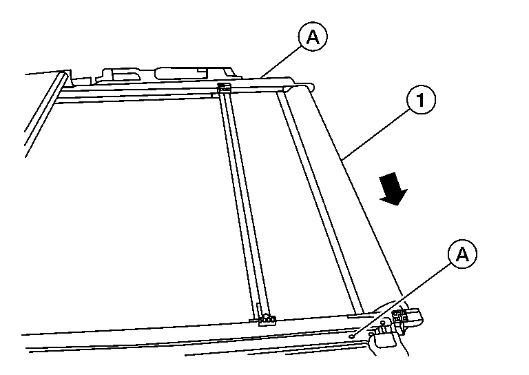
Remove moonroof unit base screws (A).
Disassemble by pulling off both moonroof unit bases (LH/RH) from the moonroof unit tracks.
Manually disengage the sunshade motor and moonroof motor assembly using a suitable tool then remove both sunshade cables and glass lid cables by pulling rearward.
Remove the cable guides (LH/RH) by pulling rearward from the moonroof unit tracks.
ASSEMBLY
CAUTION:
Do not remove the sunshade retainer pin or damage may occur.
Insert the sunshade and glass lid cables guides by sliding forward on the moonroof unit track.
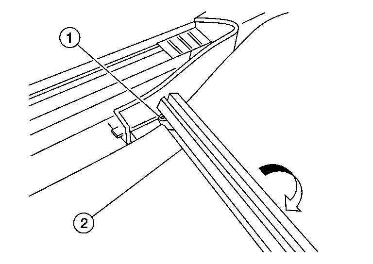
Assembly moonroof unit bases (2) (LH/RH) by pushing forward on the moonroof unit tracks (1) (LH/RH).

 NOTE:
NOTE:
RH side shown; LH similar.
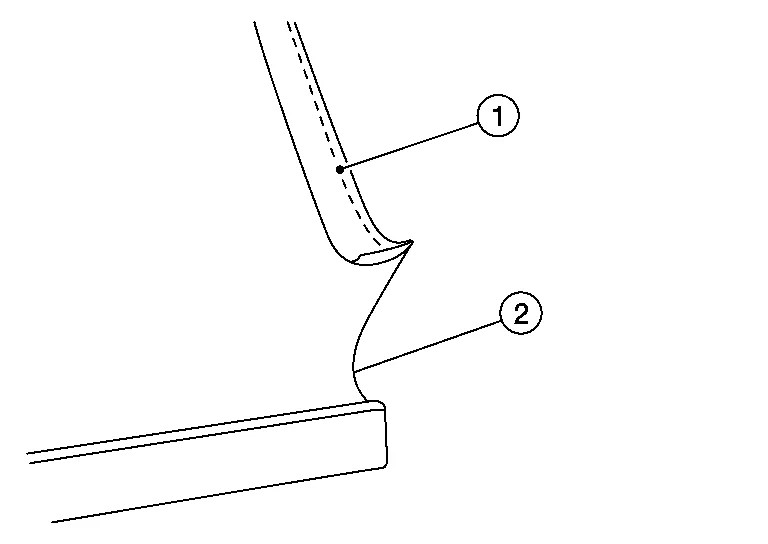
Insert sunshade black hem over lower guide (3) and under upper guide (2) on the moonroof unit bases (1) (LH/RH).

(1) Sunshade black hem.
(2) Sunshade fabric.
Assemble the sunshade by applying pressure towards the drivers and inserting both ends into the moonroof unit bases (LH/RH).
Assemble sunshade retainer.
Manually engage the sunshade motor and moonroof motor assembly using a suitable tool
With the sunshade (2) assembled remove the sunshade spring retainer pin (1).

Install panoramic roof glass. Refer to Removal and Installation.
Install moonroof unit assembly. Refer to Removal and Installation.
 Moonroof Switch
Removal and Installation
REMOVALRemove map lamp assembly. Refer to Removal and Installation.
Remove center pillar upper finisher. Refer to Removal and Installation...
 Exterior :: Precaution. Precautions
Precaution for Supplemental Restraint System (SRS) "AIR BAG" and "SEAT BELT PRE-TENSIONER"
The Supplemental Restraint System such as “AIR BAG” and “SEAT BELT PRE-TENSIONER”, used along with a front seat belt, helps to reduce the risk or severity of injury to the driver and front passenger for certain types of collisions...
Other information:
Nissan Murano (Z52) 2015-2024 Service Manual: P2127 App Sensor
DTC Description DTC DETECTION LOGIC An excessively low voltage from the APP sensor 2 is sent to ECM. An excessively high voltage from the APP sensor 2 is sent to ECM. DTC CONSULT screen terms (Trouble diagnosis content) DTC detection condition P2127 APP SEN 2/CIRC (Throttle/Pedal position sensor/switch “E” circuit low) Diagnosis condition Start engine and let it idle Signal (terminal) Voltage signal transmitted from APP sensor 2 to ECM Threshold An excessively low voltage is sent to ECM Diagnosis delay time — P2128 APP SEN 2/CIRC (Throttle/Pedal position sensor/switch “E” circuit high) Diagnosis condition Start engine and let it idle Signal (terminal) Voltage signal transmitted from APP sensor 2 to ECM Threshold An excessively high voltage is sent to ECM Diagnosis delay time — POSSIBLE CAUSEDTC P2127 Harness or connectors (APP sensor 2 circuit is open or shorted...
Nissan Murano (Z52) 2015-2024 Owners Manual: Remote starting the vehicle
To use the Remote Engine Start feature perform the following: Aim the Intelligent Key at the vehicle. Press the button to lock all doors. Within 5 seconds press and hold the button until the turn signal lights flash and the tail lamps turn on...
Categories
- Manuals Home
- Nissan Murano Owners Manual
- Nissan Murano Service Manual
- All-Wheel Drive (AWD) (if so equipped)
- Indicator lights
- Turning the AEB system on/off
- New on site
- Most important about car
Fuel gauge

The gauge indicates the approximate fuel level in the tank.
The gauge may move slightly during braking, turning, acceleration, or going up or down hills.
The gauge needle returns to 0 (Empty) after the ignition switch is placed in the OFF position.