
Nissan Murano: Exterior Lighting System :: Led Headlamp / Periodic Maintenance
Nissan Murano (Z52) 2015-2024 Service Manual / Driver Controls / Exterior Lighting System :: Led Headlamp / Periodic Maintenance
 Both Side Front Fog Lamps Are Not Turned on
Diagnosis Procedure
Both side front fog lamps are not turned ON in any condition.COMBINATION SWITCH INSPECTION
Check combination switch. Refer to Symptom Table...
 Headlamp Aiming Adjustment
Inspection
PREPARATION BEFORE ADJUSTINGBefore performing aiming adjustment, check the following:
Make sure all tires are inflated to correct pressure...
Other information:
Nissan Murano (Z52) 2015-2024 Service Manual: P2122 App Sensor
DTC Description DTC DETECTION LOGIC An excessively low voltage from the APP sensor 1 is sent to ECM. An excessively high voltage from the APP sensor 1 is sent to ECM. DTC CONSULT screen terms (Trouble diagnosis content) DTC detection condition P2122 APP SEN 1/CIRC (Throttle/Pedal position sensor/switch “D” circuit low) Diagnosis condition Start engine and let it idle Signal (terminal) Voltage signal transmitted from APP sensor 1 to ECM Threshold An excessively low voltage is sent to ECM Diagnosis delay time — P2123 APP SEN 1/CIRC (Throttle/Pedal position sensor/switch “D” circuit high) Diagnosis condition Start engine and let it idle Signal (terminal) Voltage signal transmitted from APP sensor 1 to ECM Threshold An excessively high voltage is sent to ECM Diagnosis delay time — POSSIBLE CAUSEDTC P2122 Harness or connectors (APP sensor 1 circuit is open or shorted...
Nissan Murano (Z52) 2015-2024 Service Manual: Component Parts. Tire Pressure Monitoring System
Component Parts Location A. LH side of instrument panel (view with instrument panel removed) B. Combination meter (view with combination meter removed) C. RH side of instrument panel (view with instrument panel removed) D. Wheel (view with wheel and tire removed) E...
Categories
- Manuals Home
- Nissan Murano Owners Manual
- Nissan Murano Service Manual
- High Beam Assist (if so equipped)
- Tire rotation
- Rear bench seat adjustment
- New on site
- Most important about car
LATCH (Lower Anchors and Tethers for CHildren) system
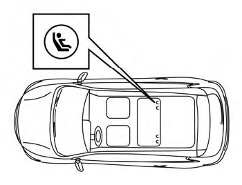
LATCH system lower anchor locations - bench seat
Your vehicle is equipped with special anchor points that are used with LATCH system compatible child restraints. This system may also be referred to as the ISOFIX or ISOFIX compatible system. With this system, you do not have to use a vehicle seat belt to secure the child restraint unless the combined weight of the child and child restraint exceeds 65 lbs. (29.5 kg). If the combined weight of the child and child restraint is greater than 65 lbs. (29.5 kg), use the vehicle’s seat belt (not the lower anchors) to install the child restraint. Be sure to follow the child restraint manufacturer’s instructions for installation.

Copyright © 2026 www.nimurano.com