Nissan Murano: Road Wheels & Tires :: System Description / Component Parts. Tire Pressure Monitoring System
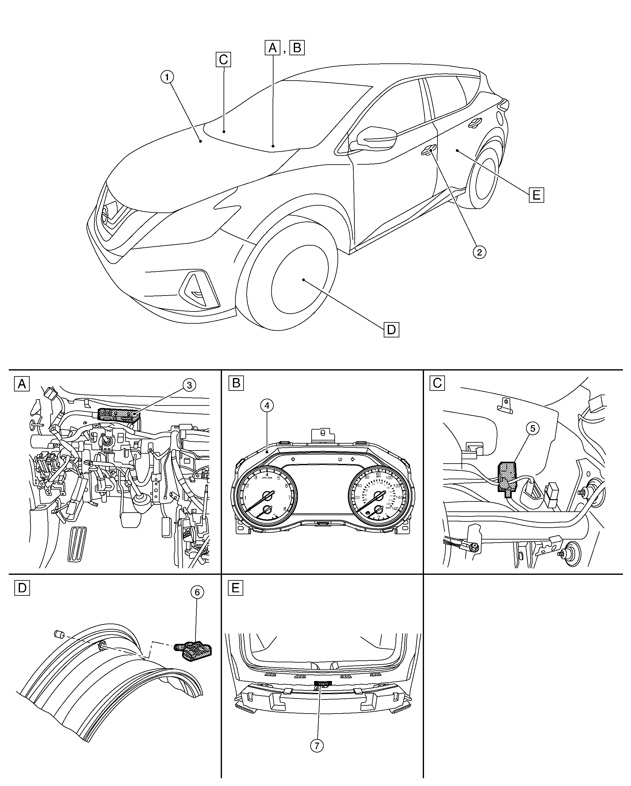
| A. |
LH side of instrument panel (view with instrument panel removed) |
B. |
Combination meter (view with combination meter removed) |
C. |
RH side of instrument panel (view with instrument panel removed) |
| D. |
Wheel (view with wheel and tire removed) |
E. |
Rear of Nissan Murano vehicle (view with rear bumper fascia removed) |
||
| No. | Component | Function |
|---|---|---|
| 1. | ABS (Anti-lock Braking System) actuator and electric unit (control unit) |
Mainly transmits the Nissan Murano vehicle speed signal to BCM via CAN communication. Refer to Component Parts Location for detailed component location. |
| 2. | Front outside handle assembly LH [antenna (RH side similar)] | Refer to Outside Key Antennas. |
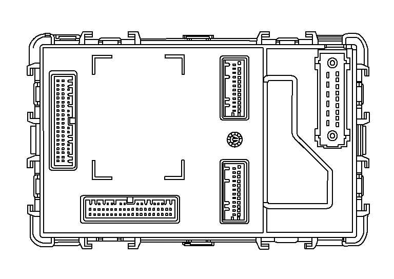
| 3. | BCM (Body Control Module) | Refer to BCM. |
| 4. | Combination meter |
Mainly receives the following signals from BCM via CAN communication:
The combination meter will display the low tire pressure warning lamp when a low tire pressure or system malfunction is detected by the BCM. A warning message will also be displayed in the information display. Refer to Component Parts Location for detailed component location. |
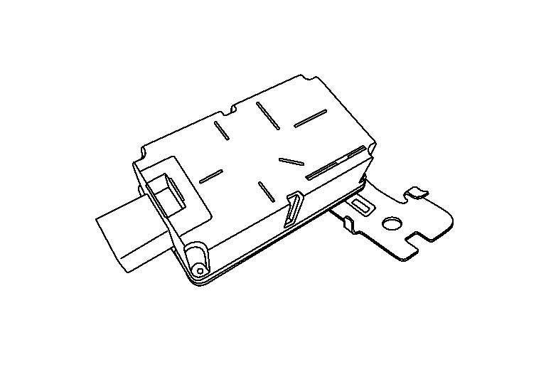
| 5. | Remote keyless entry receiver | Refer to Remote Keyless Entry Receiver. |
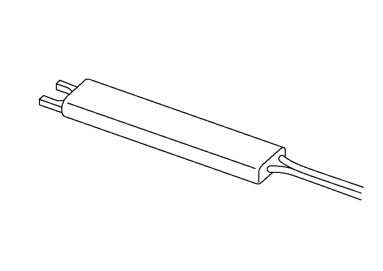
| 6. | Tire pressure sensor | Refer to Tire Pressure Sensor. |
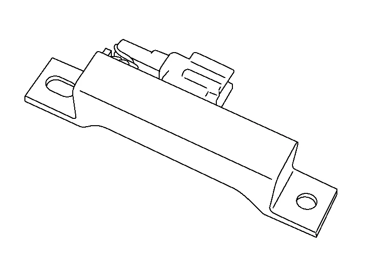
| 7. | Outside key antenna (rear bumper) | Refer to Outside Key Antennas. |
-
The BCM is installed in the LH side of the instrument panel.
-
The BCM reads the tire pressure signal received by the remote keyless entry receiver. In addition, the BCM also uses the outside key antennas (driver side, passenger side and rear bumper) to identify the location of the tire pressure sensors.
-
The BCM has a self-diagnosis function used to detect system malfunctions.
A tire pressure sensor (1) integrated with a valve is installed in each wheel (2), and transmits a detected air pressure signal in the form of a radio wave. The radio signal is received by the remote keyless entry receiver.
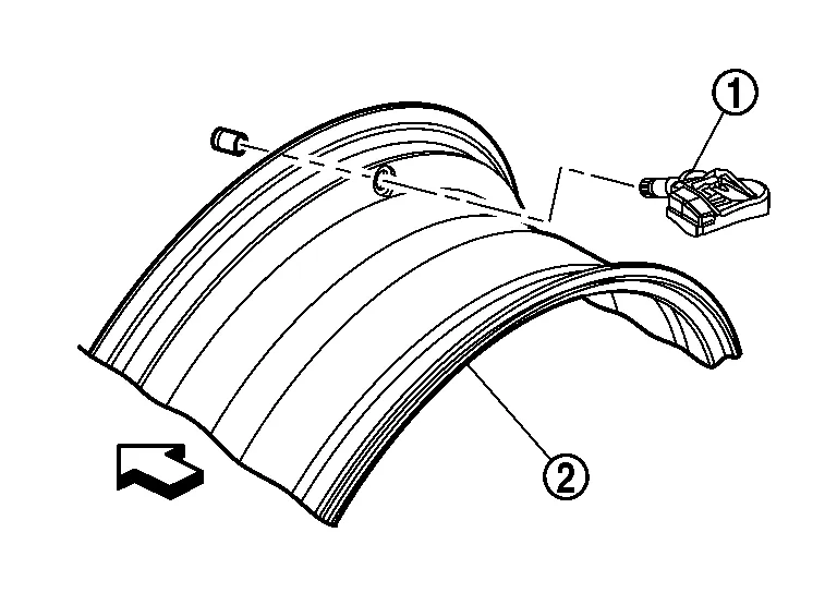
| : Outside |
The remote keyless entry receiver receives the tire pressure signal transmitted by the tire pressure sensor in each wheel.
-
For vehicles equipped with individual tire pressure display in the combination meter, the outside key antennas (LH, RH and rear bumper) are used by the BCM to identify the location of the tire pressure sensor.
-
Antenna LH and RH are installed in the front outside handle assembly LH and RH.
-
Outside key antenna (rear bumper) is installed in the center of rear bumper.

 System
System Description
When the vehicle has reached a speed of 25 MPH (40 km/h) or greater, the BCM receives a signal transmitted from the tire pressure sensors/transmitters installed in each wheel...
Other information:
Nissan Murano (Z52) 2015-2024 Service Manual: System Settings Cannot Be Turned On/off
Diagnosis Procedure System setting is not selectable on the combination meter. Intelligent Forward Collision Warning (I-FCW) Intelligent Drive Alertness (I-DA) Traffic Sign Recognition (TSR) Rear Automatic Braking (RAB) Lane Departure Warning (LDW) Blind Spot Warning (BSW) Intelligent Lane Intervention (I-LI) Rear Cross Traffic Alert (RCTA) NOTE: When the ignition switch is in ACC position, each system settings cannot be changed...
Nissan Murano (Z52) 2015-2024 Service Manual: B13ec Factory Mode
DTC Description DTC DETECTION LOGIC DTC No. CONSULT screen terms (Trouble diagnosis content) DTC detection condition B13EC–52 Factory mode (AV control unit) [—] Diagnosis condition When ignition switch is ON. Signal (terminal) – Threshold – Diagnosis delay time 30 seconds or more B13EC–55 [CONFIG] Diagnosis condition When ignition switch is ON...
Categories
- Manuals Home
- Nissan Murano Owners Manual
- Nissan Murano Service Manual
- Memory storage function (key-link)
- Indicator lights
- Vehicle Dynamic Control (VDC) OFF switch
- New on site
- Most important about car
Seatback pockets

Theremaybe one or two seatback pockets located on the back of the driver and passenger seats. The pockets can be used to store maps.
WARNING