Nissan Murano: Parking Brake System :: Removal and Installation / Parking Brake Control
Nissan Murano (Z52) 2015-2024 Service Manual / Brakes / Parking Brake System :: Removal and Installation / Parking Brake Control
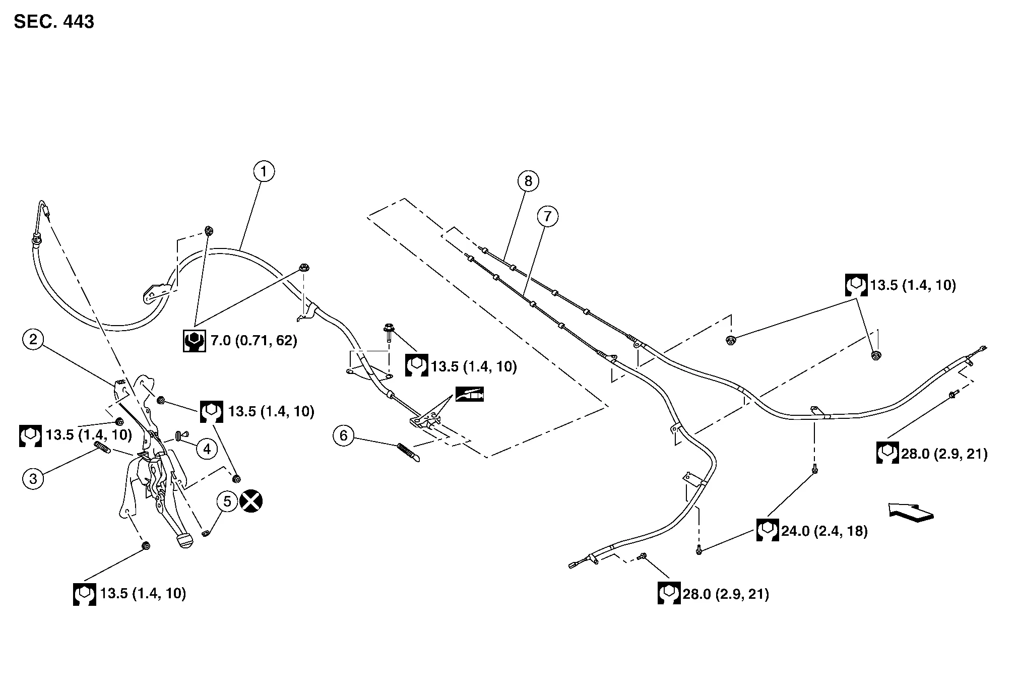
| 1. | Front cable | 2. | Parking brake pedal assembly | 3. | Parking brake pedal return spring |
| 4. | Parking brake switch | 5. | Adjusting nut | 6. | Return spring |
| 7. | Rear cable (LH) | 8. | Rear cable (RH) | Front |
WARNING:
-
Always work from the side of air bag module. Do not work in front of it.
-
Do not use air tools or electric tools for servicing.
REMOVAL
Remove lower instrument panel LH. Refer to Removal and Installation.
Place fuse box aside.
Disconnect harness connector from parking brake switch.
Remove parking brake pedal assembly nuts and place parking brake pedal assembly aside.
Remove adjusting nut from parking brake pedal.
Separate front cable from parking brake pedal.
Remove parking brake pedal assembly.
Remove parking brake switch if necessary.
INSTALLATION
Installation is in the reverse order of removal.
CAUTION:
Do not reuse the adjusting nut.
Adjust parking brake with new adjusting nut. Refer to Inspection and Adjustment.

 Parking Brake Front Cable
Removal and Installation
REMOVALRemove parking brake control. Refer to Removal and Installation.
NOTE:
It is not necessary to remove parking brake switch...
Other information:
Nissan Murano (Z52) 2015-2024 Service Manual: Security Control System :: Precaution. Precautions
Precaution for Supplemental Restraint System (SRS) "AIR BAG" and "SEAT BELT PRE-TENSIONER" The Supplemental Restraint System such as “AIR BAG” and “SEAT BELT PRE-TENSIONER”, used along with a front seat belt, helps to reduce the risk or severity of injury to the driver and front passenger for certain types of collisions...
Nissan Murano (Z52) 2015-2024 Service Manual: U1000 Can Comm Circuit
DTC Description DESCRIPTIONCAN (Controller Area Network) is a serial communication system for real-time application. It is an on-Nissan Murano vehicle multiplex communication system with high data communication speed and excellent error detection ability...
Categories
- Manuals Home
- Nissan Murano Owners Manual
- Nissan Murano Service Manual
- System malfunction
- Intelligent Forward Collision Warning (I-FCW)
- Checking engine oil level
- New on site
- Most important about car
Copyright © 2026 www.nimurano.com