Nissan Murano: Dtc/circuit Diagnosis / P0456 Evap Control System
DTC DETECTION LOGIC
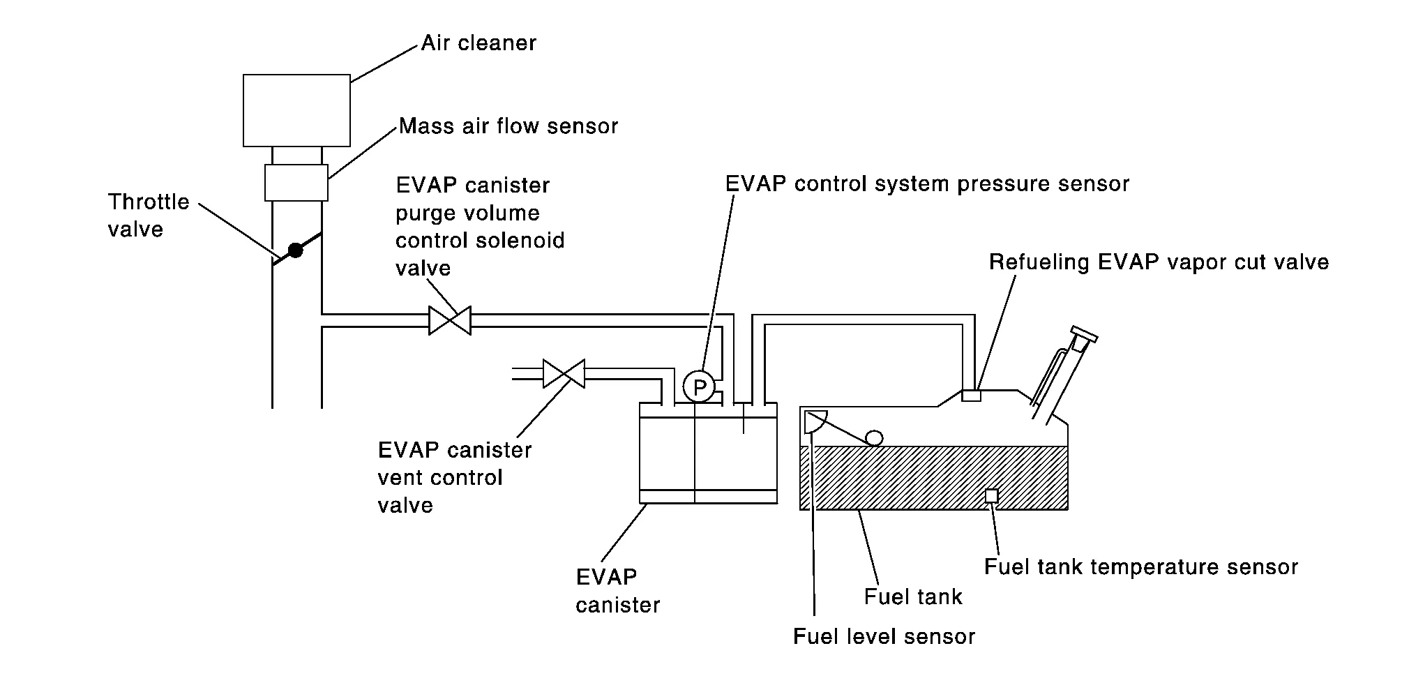
This diagnosis detects leaks in the EVAP line between fuel tank and EVAP canister purge volume control solenoid valve, using the negative pressure caused by decrease of fuel temperature in the fuel tank after turning ignition switch OFF.
If ECM judges there are no leaks, the diagnosis will be OK.
-
EVAP system has a leak.
-
EVAP system does not operate properly.
| DTC |
CONSULT screen terms (Trouble diagnosis content) |
DTC detection condition | ||
| P0456 |
EVAP VERY SML LEAK [Evaporative emission system leak detected (very small leak)] |
1 | Diagnosis condition | — |
| Signal (terminal) | — | |||
| Threshold | EVAP system has a leak | |||
| Diagnosis delay time | — | |||
| 2 | Diagnosis condition | — | ||
| Signal (terminal) | — | |||
| Threshold | EVAP system does not operate properly | |||
| Diagnosis delay time | — | |||
CAUTION:
-
Use only a genuine NISSAN fuel filler cap as a replacement. If an incorrect fuel filler cap is used, the MIL may come on.
-
If the fuel filler cap is not tightened properly, the MIL may come on.
-
Use only a genuine NISSAN rubber tube as a replacement.
POSSIBLE CAUSE
-
Incorrect fuel tank vacuum relief valve
-
Incorrect fuel filler cap used
-
Fuel filler cap remains open or fails to close.
-
Foreign matter caught in fuel filler cap.
-
Leak is in line between intake manifold and EVAP canister purge volume control solenoid valve.
-
Foreign matter caught in EVAP canister vent control valve.
-
EVAP canister or fuel tank leaks
-
EVAP purge line (pipe and rubber tube) leaks
-
EVAP purge line rubber tube bent
-
Loose or disconnected rubber tube
-
EVAP canister vent control valve and the circuit
-
EVAP canister purge volume control solenoid valve and the circuit
-
Fuel tank temperature sensor
-
O-ring of EVAP canister vent control valve is missing or damaged
-
EVAP canister is saturated with water
-
EVAP control system pressure sensor
-
Refueling EVAP vapor cut valve
-
ORVR system leaks
-
Fuel level sensor and the circuit
-
Foreign matter caught in EVAP canister purge volume control solenoid valve
FAIL-SAFE
Not applicable
PRECONDITIONING
If DTC Confirmation Procedure has been previously conducted, always perform the following before conducting the next test.
-
Turn ignition switch OFF and wait at least 10 seconds.
-
Turn ignition switch ON.
-
Turn ignition switch OFF and wait at least 10 seconds.
Do you have CONSULT?
YES>>GO TO 2.
NO>>GO TO 4.
PERFORM DTC CONFIRMATION PROCEDURE-I
 With CONSULT
-
Turn ignition switch ON and select “EVAP DIAG READY” in “DATA MONITOR” mode with CONSULT.
-
Start engine and wait at idle until “OFF” of “EVAP DIAG READY” changes to “ON”.
 NOTE:
NOTE:
It will take at most 2 hours until “OFF” of “EVAP DIAG READY” changes to “ON”.
-
Turn ignition switch OFF and wait at least 90 minutes.
NOTE:
Never turn ignition switch ON during 90 minutes.
-
Turn ignition switch ON and select “EVAP LEAK DIAG” in “DATA MONITOR” mode with CONSULT.
-
Check that “EVAP LEAK DIAG” indication.
Which is displayed on CONSULT?
CMPLT>>GO TO 3.
YET>>Perform DTC CONFIRMATION PROCEDURE again. GO TO 1.
PERFORM DTC CONFIRMATION PROCEDURE-II
Check 1st trip DTC.
Is 1st trip DTC detected?
YES>>Go to Diagnosis Procedure.
NO>>To check malfunction symptom before repair: Refer to Intermittent Incident.
NO>>Confirmation after repair: INSPECTION END
PERFORM DTC CONFIRMATION PROCEDURE
 With GST
-
Start engine and wait engine idle for at least 2 hours.
-
Turn ignition switch OFF and wait at least 90 minutes.
NOTE:
Never turn ignition switch ON during 90 minutes.
-
Turn ignition switch ON.
-
Check 1st trip DTC.
Is 1st trip DTC detected?
YES>>Go to Diagnosis Procedure.
NO>>To check malfunction symptom before repair: Refer to Intermittent Incident.
NO>>Confirmation after repair: INSPECTION END
CHECK FUEL FILLER CAP DESIGN
-
Turn ignition switch OFF.
-
Check for genuine NISSAN fuel filler cap design.
Is the inspection result normal?
YES>>GO TO 2.
NO>>Replace with genuine NISSAN fuel filler cap.
CHECK FUEL FILLER CAP INSTALLATION
Check that the cap is tightened properly by rotating the cap clockwise.
Is the inspection result normal?
YES>>GO TO 3.
NO>>Open fuel filler cap, then clean cap and fuel filler neck threads using air blower. Then retighten until ratcheting sound is heard.
CHECK FUEL FILLER CAP FUNCTION
Check for air releasing sound while opening the fuel filler cap.
Is the inspection result normal?
YES>>GO TO 5.
NO>>GO TO 4.
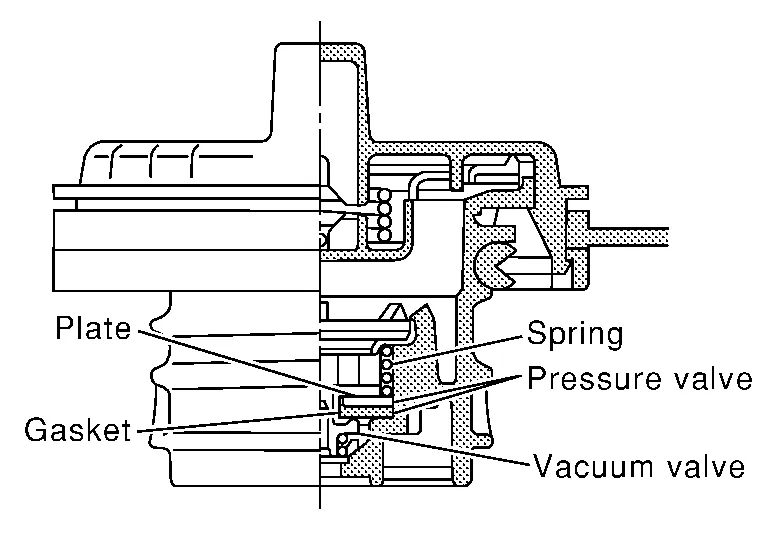
CHECK FUEL TANK VACUUM RELIEF VALVE
Refer to Component Inspection.
Is the inspection result normal?
YES>>GO TO 5.
NO>>Replace fuel filler cap with a genuine one.
CHECK FOR EVAP LEAK
Refer to Work Procedure.
Is there any leak in EVAP line?
YES>>Repair or replace.
NO>>GO TO 6.
CHECK EVAP CANISTER VENT CONTROL VALVE
Check the following.
-
EVAP canister vent control valve is installed properly.
Refer to Removal and Installation.
-
EVAP canister vent control valve.
Refer to Component Inspection.
Is the inspection result normal?
YES>>GO TO 7.
NO>>Repair or replace EVAP canister vent control valve and O-ring.
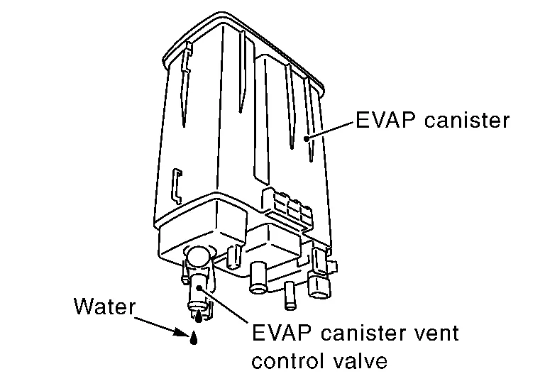
CHECK IF EVAP CANISTER SATURATED WITH WATER
-
Remove EVAP canister with EVAP canister vent control valve and EVAP control system pressure sensor attached.
-
Check if water will drain from the EVAP canister.
Does water drain from EVAP canister?
YES>>GO TO 8.
NO>>With CONSULT: GO TO 10.
NO>>Without CONSULT: GO TO 11.
CHECK EVAP CANISTER
Weigh the EVAP canister assembly with the EVAP canister vent control valve and EVAP control system pressure sensor attached.
The weight should be less than 2.1 kg (4.6 lb).
Is the inspection result normal?
YES>>With CONSULT: GO TO 10.
YES>>Without CONSULT: GO TO 11.
NO>>GO TO 9.
DETECT MALFUNCTIONING PART
Check the following.
-
EVAP canister for damage
-
EVAP hose between EVAP canister and Nissan Murano vehicle frame for clogging or poor connection
>>
Repair hose or replace EVAP canister.
CHECK EVAP CANISTER PURGE VOLUME CONTROL SOLENOID VALVE OPERATION
With CONSULT
-
Disconnect vacuum hose to EVAP canister purge volume control solenoid valve at EVAP service port.
-
Start engine and let it idle.
-
Select “PURG VOL CONT/V” in “ACTIVE TEST” mode.
-
Touch “Qu” on CONSULT screen to increase “PURG VOL CONT/V” opening to 100%.
-
Check vacuum hose for vacuum.
Vacuum should exist.
Is the inspection result normal?
YES>>GO TO 13.
NO>>GO TO 12.
CHECK EVAP CANISTER PURGE VOLUME CONTROL SOLENOID VALVE OPERATION
 Without CONSULT
-
Start engine and warm it up to normal operating temperature.
-
Stop engine.
-
Disconnect vacuum hose to EVAP canister purge volume control solenoid valve at EVAP service port.
-
Start engine and let it idle for at least 80 seconds.
-
Check vacuum hose for vacuum when revving engine up to 2,000 rpm.
Vacuum should exist.
Is the inspection result normal?
YES>>GO TO 13.
NO>>GO TO 12.
CHECK VACUUM HOSE
Check vacuum hoses for clogging or disconnection. Refer to System Description.
Is the inspection result normal?
YES>>GO TO 13.
NO>>Repair or reconnect the hose.
CHECK EVAP CANISTER PURGE VOLUME CONTROL SOLENOID VALVE
Refer to Component Inspection.
Is the inspection result normal?
YES>>GO TO 14.
NO>>Replace EVAP canister purge volume control solenoid valve.
CHECK FUEL TANK TEMPERATURE SENSOR
Refer to Component Inspection.
Is the inspection result normal?
YES>>GO TO 15.
NO>>Replace fuel level sensor unit.
CHECK EVAP CONTROL SYSTEM PRESSURE SENSOR
Refer to Component Inspection.
Is the inspection result normal?
YES>>GO TO 16.
NO>>Replace EVAP control system pressure sensor.
CHECK EVAP PURGE LINE
Check EVAP purge line (pipe, rubber tube, fuel tank and EVAP canister) for cracks or improper connection.
Refer to System Description.
Is the inspection result normal?
YES>>GO TO 17.
NO>>Repair or reconnect the hose.
CLEAN EVAP PURGE LINE
Clean EVAP purge line (pipe and rubber tube) using air blower.
>>
GO TO 18.
CHECK EVAP/ORVR LINE
Check EVAP/ORVR line between EVAP canister and fuel tank for clogging, kink, looseness and improper connection. For location, refer to On Board Refueling Vapor Recovery (ORVR).
Is the inspection result normal?
YES>>GO TO 19.
NO>>Repair or replace hoses and tubes.
CHECK RECIRCULATION LINE
Check recirculation line between fuel filler tube and fuel tank for clogging, kink, cracks, looseness and improper connection.
Is the inspection result normal?
YES>>GO TO 20.
NO>>Repair or replace hose, tube or fuel filler tube.
CHECK REFUELING EVAP VAPOR CUT VALVE
Refer to Component Inspection.
Is the inspection result normal?
YES>>GO TO 21.
NO>>Replace refueling EVAP vapor cut valve with fuel tank.
CHECK FUEL LEVEL SENSOR
Refer to Component Inspection.
Is the inspection result normal?
YES>>INSPECTION END
NO>>Replace fuel level sensor unit.
CHECK FUEL FILLER CAP
-
Turn ignition switch OFF.
-
Remove fuel filler cap. Refer to Exploded View (FWD models) or Exploded View (AWD models).
-
Wipe clean valve housing.
-
Install fuel filler cap adapter (commercial service tool) to fuel filler cap.
-
Check valve opening pressure and vacuum.
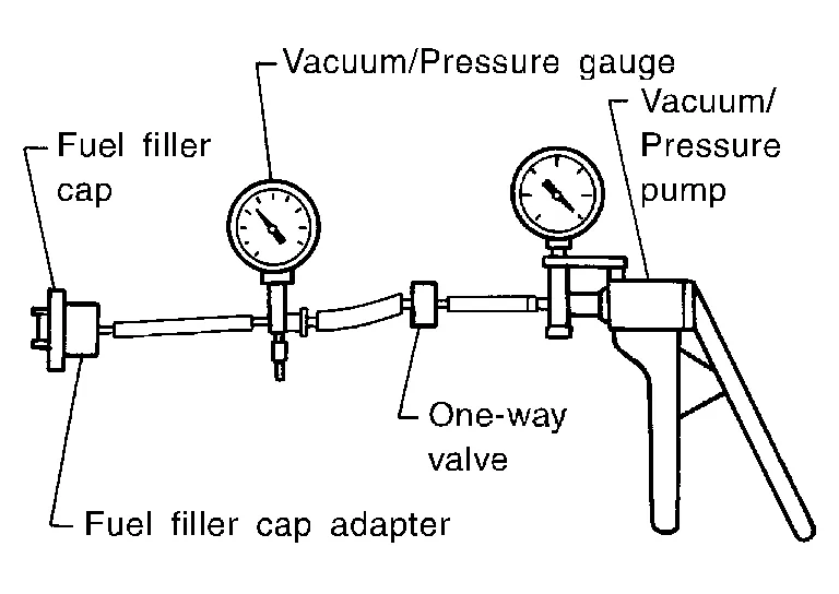
Pressure: 15.3 - 20.0 kPa (0.156 - 0.204 kg/cm2, 2.22 - 2.90 psi) Vacuum: −6.0 to −3.3 kPa (−0.061 to −0.034 kg/cm2, −0.87 to −0.48 psi)
Is the inspection result normal?
YES>>INSPECTION END
NO>>GO TO 2.
REPLACE FUEL FILLER CAP
Replace fuel filler cap. Refer to Exploded View (FWD models) or Exploded View (AWD models).
CAUTION:
Use only a genuine fuel filler cap as a replacement. If an incorrect fuel filler cap is used, the MIL may illuminate.
>>
INSPECTION END
 P0454 Evap Control System Pressure Sensor
DTC Description
DTC DETECTION LOGICECM detects a sloshing signal from the EVAP control system pressure sensor. DTC
CONSULT screen terms
(Trouble diagnosis content)
DTC detection condition
P0454
EVAP SYS PRES SEN
(Evaporative emission system pressure sensor/switch range/performance)
Diagnosis condition
—
Signal (terminal)
Voltage signal transmitted from EVAP control system pressure sensor to ECM
Threshold
ECM detects a sloshing signal from the EVAP control system pressure sensor
Diagnosis delay time
—
POSSIBLE CAUSE
Harness or connectors
(EVAP control system pressure sensor circuit is shorted...
 P0460 Fuel Level Sensor
DTC Description
DTC DETECTION LOGICWhen the vehicle is parked, the fuel level in the fuel tank is naturally stable. It means that output signal of the fuel level sensor does not change...
Other information:
Nissan Murano (Z52) 2015-2024 Service Manual: Heater & Air Conditioning System :: Basic Inspection. Diagnosis and Repair Workflow
Workflow OVERALL SEQUENCEDETAILED FLOWINTERVIEW CUSTOMER Interview the customer to obtain as much information as possible about the conditions and environment under which the malfunction occurred. >> GO TO 2. SYMPTOM CHECK Verify symptoms. >> GO TO 3...
Nissan Murano (Z52) 2015-2024 Service Manual: Abs Actuator and Electric Unit (control Unit)
Exploded View 1. ABS actuator and electric unit (control unit) 2. Bracket A. To rear (RH) brake caliper. Refer to Exploded View. B. From master cylinder secondary side. Refer to Exploded View. C. Refer to Removal and Installation. D...
Categories
- Manuals Home
- Nissan Murano Owners Manual
- Nissan Murano Service Manual
- Power Steering Fluid (PSF)
- GAS STATION INFORMATION
- Shift lock release
- New on site
- Most important about car
Luggage hooks

When securing items using luggage hooks located on the back of the seat or side finisher do not apply a load over more than 6.5 lbs. (29 N) to a single hook.
The luggage hooks that are located on the floor should have loads less than 110 lbs. (490 N) to a single hook.