Nissan Murano: Dtc/circuit Diagnosis / P0011 Ivt Control
DTC DETECTION LOGIC
There is a gap between angle of target and phase-control angle degree.
| DTC |
CONSULT screen terms (Trouble diagnosis content) |
DTC detection condition | |
| P0011 |
INT/V TIM CONT-B1 (“A” Camshaft Position - Timing Over-Advanced or System Performance bank 1) |
Diagnosis condition | — |
| Signal (terminal) | Camshaft position sensor signal | ||
| Threshold | During the advanced control of intake valve timing control, the angle difference between actual angle and target angle is 13 degrees or more. | ||
| Diagnosis delay time | 6 seconds or more | ||
| P0021 |
INT/V TIM CONT-B2 (“B” Camshaft Position - Timing Over-Advanced or System Performance bank 2) |
Diagnosis condition | — |
| Signal (terminal) | Camshaft position sensor signal | ||
| Threshold | During the advanced control of intake valve timing control, the angle difference between actual angle and target angle is 13 degrees or more. | ||
| Diagnosis delay time | 6 seconds or more | ||
POSSIBLE CAUSE
-
Crankshaft position sensor (POS)
-
Camshaft position sensor (PHASE)
-
Intake valve timing control solenoid valve
-
Accumulation of debris to the signal pick-up portion of the camshaft
-
Timing chain installation
-
Foreign matter caught in the oil groove for intake valve timing control
FAIL-SAFE
| Engine operating condition in fail-safe mode | ||
|---|---|---|
| Fail safe mode | Nissan Murano Vehicle behavior | |
| Intake valve timing control |
|
|
CHECK DTC PRIORITY
If DTC P0011 or P0021 is displayed with DTC P0075 or P0081, first perform the trouble diagnosis for DTC P0075 or P0081.
Is applicable DTC detected?
YES>>Perform diagnosis of applicable.
-
DTC P0075: Refer to DTC Description.
-
DTC P0081: Refer to DTC Description.
GO TO 2.
PRECONDITIONING
If DTC Confirmation Procedure has been previously conducted, always perform the following before conducting the next test.
-
Turn ignition switch OFF and wait at least 10 seconds.
-
Turn ignition switch ON.
-
Turn ignition switch OFF and wait at least 10 seconds.
TESTING CONDITION:
Before performing the following procedure, confirm that battery voltage is between 10 V and 16 V at idle.
>>
GO TO 3.
PERFORM DTC CONFIRMATION PROCEDURE-I
 With CONSULT
-
Turn ignition switch ON and select “DATA MONITOR” mode with CONSULT.
-
Start engine and warm it up to the normal operating temperature.
-
Maintain the following conditions for at least 13 consecutive seconds. Hold the accelerator pedal as steady as possible.
ENG SPEED 1,200 - 2,000 rpm COOLANT TEMP/S More than 60°C (140°F) Selector lever P or N position -
Stop Nissan Murano vehicle with engine running and let engine idle for 13 seconds.
-
Check 1st trip DTC.
 With GST
Follow the procedure “With CONSULT” above.
Is 1st trip DTC detected?
YES>>Proceed to Diagnosis Procedure
NO>>GO TO 4.
PERFORM DTC CONFIRMATION PROCEDURE-II
With CONSULT
-
Maintain the following conditions for at least 20 consecutive seconds.
ENG SPEED 1,200 - 3,175 rpm (A constant rotation is maintained.) COOLANT TEMP/S More than 64°C (147°F) Selector lever D position Driving location uphill Driving Nissan Murano vehicle uphill
(Increased engine load will help maintain the driving conditions required for this test.)CAUTION:
Always drive at a safe speed.
-
Check 1st trip DTC.
With GST
Follow the procedure “With CONSULT” above.
Is 1st trip DTC detected?
YES>>Proceed to Diagnosis Procedure
NO>>To check malfunction symptom before repair: Refer to Intermittent Incident.
NO>>Confirmation after repair: INSPECTION END
CHECK DTC PRIORITY
If DTC P0011 or P0021 is displayed with DTC P0075 or P0081, first perform the trouble diagnosis for DTC P0075 or P0081.
Is applicable DTC detected?
YES>>Perform diagnosis of applicable.
-
DTC P0075: Refer to DTC Description.
-
DTC P0081: Refer to DTC Description.
GO TO 2.
CHECK OIL PRESSURE WARNING LAMP
-
Start engine.
-
Check oil pressure warning lamp and confirm it is not illuminated.

Is oil pressure warming lamp illuminated?
YES>>Check the engine oil level. Refer to Inspection.
NO>>GO TO 3.
CHECK INTAKE VALVE TIMING CONTROL SOLENOID VALVE
Check intake valve timing control solenoid valve. Refer to Component Inspection.
Is the inspection result normal?
YES>>GO TO 4.
NO>>Replace malfunctioning intake valve timing control solenoid valve. Refer to Exploded View.
CHECK CRANKSHAFT POSITION SENSOR (POS)
Check crankshaft position sensor (POS). Refer to Component Inspection.
Is the inspection result normal?
YES>>GO TO 5.
NO>>Replace crankshaft position sensor (POS). Refer to Exploded View.
CHECK CAMSHAFT POSITION SENSOR (PHASE)
Check camshaft position sensor (PHASE). Refer to Component Inspection.
Is the inspection result normal?
YES>>GO TO 6.
NO>>Replace malfunctioning camshaft position sensor (PHASE). Refer to Exploded View.
CHECK CAMSHAFT (INTAKE)
Check the following.
-
Accumulation of debris on the signal plate of camshaft rear end

-
Chipping signal plate of camshaft rear end
Is the inspection result normal?
YES>>GO TO 7.
NO>>Remove debris and clean the signal plate of camshaft rear end or replace camshaft. Refer to Removal and Installation.
CHECK TIMING CHAIN INSTALLATION
Check service records for any recent repairs that may cause timing chain misalignment.
Are there any service records that may cause timing chain misalignment?
YES>>Check timing chain installation. Refer to Removal and Installation.
NO>>GO TO 8.
CHECK LUBRICATION CIRCUIT
Check lubrication circuit. Refer to Inspection.
Is the inspection result normal?
YES>>INSPECTION END
NO>>Clean lubrication line.
CHECK INTAKE VALVE TIMING CONTROL SOLENOID VALVE-I
-
Turn ignition switch OFF.
-
Disconnect intake valve timing control solenoid valve harness connector.
-
Check resistance between intake valve timing control solenoid valve terminals as per the following.
Intake valve timing control solenoid valve Condition
Resistance + − Terminal 1 2 Temperature 20°C (68°F) 7.0 – 7.8 Ω 1 Ground ∞
(Continuity should not exist)2
Is the inspection result normal?
YES>>GO TO 2.
NO>>Replace malfunctioning intake valve timing control solenoid valve. Refer to Exploded View.
CHECK INTAKE VALVE TIMING CONTROL SOLENOID VALVE-II
-
Remove intake valve timing control solenoid valve. Refer to Exploded View.
-
Provide 12 V DC between intake valve timing control solenoid valve terminals 1 and 2, and then interrupt it. Check that the plunger moves as shown in the figure.
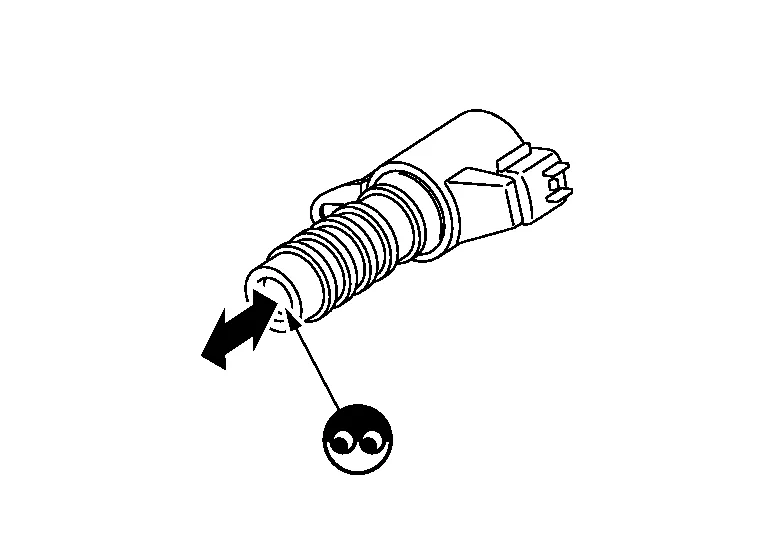
CAUTION:
Never apply 12 V DC continuously for 5 seconds or more. Doing so may result in damage to the coil in intake valve timing control solenoid valve.
 NOTE:
NOTE:
Always replace O-ring when intake valve timing control solenoid valve is removed.
Is the inspection result normal?
YES>>INSPECTION END
NO>>Replace malfunctioning intake valve timing control solenoid valve. Refer to Exploded View.
 U1044 Eng Comm Circuit
DTC Description
DTC DETECTION LOGICA signal voltage of LIN communication between ECM and generator is excessively low or excessively high. DTC
CONSULT screen terms
(Trouble diagnosis content)
DTC detection condition
U1044
ENG COMM CIRCUIT
(Engine communication circuit)
Diagnosis condition
Ignition switch ON
Signal (terminal)
Signal voltage of LIN communication
Threshold
Signal voltage between ECM and generator is excessively low or excessively high
Diagnosis delay time
—
POSSIBLE CAUSE
Harness or connectors
(LIN communication circuit is open or shorted...
 P0014 Evt Control
DTC Description
DTC DETECTION LOGICThere is a gap between angle of target and phase-control angle degree. DTC
CONSULT screen terms
(Trouble diagnosis content)
DTC detection condition
P0014
EXH/V TIM CONT-B1
[Exhaust valve timing control performance (bank 1)]
Diagnosis condition
—
Signal (terminal)
Exhaust valve timing control position sensor signal
Threshold
During the advanced control of exhaust valve timing control, the angle difference between actual angle and target angle is 13 degrees or more...
Other information:
Nissan Murano (Z52) 2015-2024 Service Manual: Automatic Back Door Control Module
Removal and Installation CAUTION: Replace the automatic back door control module if it has been dropped or sustained an impact. REMOVALRemove luggage side lower finisher (LH). Refer to Removal and Installation. Disconnect the harness connectors from the automatic back door control module...
Nissan Murano (Z52) 2015-2024 Service Manual: Axle and Suspension Parts
Inspection Check front and rear axle and suspension parts for excessive play, cracks, wear or other damage. Shake each wheel to check for excessive play. Check wheel bearings for smooth operation. Check axle and suspension nuts and bolts for looseness...
Categories
- Manuals Home
- Nissan Murano Owners Manual
- Nissan Murano Service Manual
- Rear bench seat adjustment
- System malfunction
- Power Steering Fluid (PSF)
- New on site
- Most important about car
Fuel gauge

The gauge indicates the approximate fuel level in the tank.
The gauge may move slightly during braking, turning, acceleration, or going up or down hills.
The gauge needle returns to 0 (Empty) after the ignition switch is placed in the OFF position.