Nissan Murano: System / Nissan Vehicle Immobilizer System-Nats
SYSTEM DIAGRAM
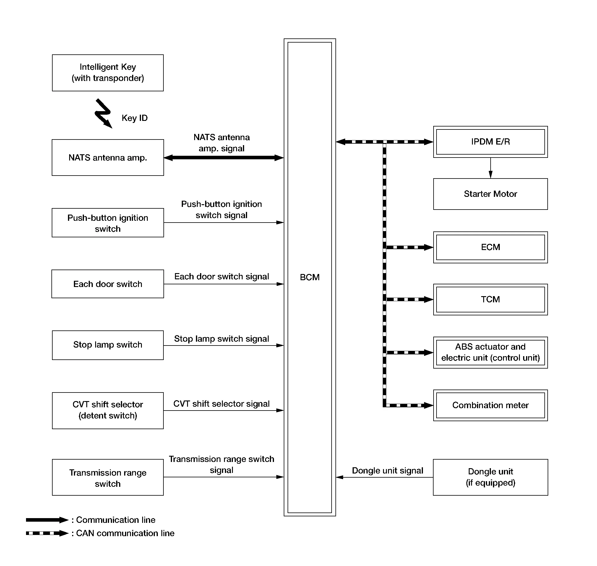
INPUT SIGNAL AND OUTPUT SIGNAL CHART
| Component | Signal description |
|---|---|
| ECM |
Mainly transmits the following signal to BCM and combination meter via CAN communication.
Mainly receives the following signal from BCM via CAN communication.
|
| IPDM E/R |
Mainly receives the following signal from BCM via CAN communication.
|
| ABS actuator and electric unit (control unit) |
Mainly transmits the following signal to BCM via CAN communication.
|
| Combination meter |
Mainly transmits the following signal to BCM, ECM and IPDM E/R via CAN communication.
|
| TCM (Transmission Control Module) |
Mainly receives the following signal from BCM via CAN communication.
|
SYSTEM DESCRIPTION
-
The NISSAN VEHICLE IMMOBILIZER SYSTEM-NATS [NVIS (NATS)] prevents the engine from being started by Intelligent Key whose ID is not registered to the Nissan Murano vehicle (BCM). It has higher protection against auto theft involving the duplication of mechanical keys.
-
The ignition key integrated in the Intelligent Key cannot start the engine. When the Intelligent Key battery is discharged, the NVIS (NATS) ID verification is performed between the transponder integrated with Intelligent Key and BCM via NATS antenna amp., when the Intelligent Key backside is contacted to push-button ignition switch. If the verification results are OK, the engine start operation can be performed by the push-button ignition switch operation.
-
Locate the security indicator lamp and apply the anti-theft system equipment sticker that warns that the NVIS (NATS) is on-board the model.
-
Security indicator lamp always blinks when the power supply position is any position other than ON.
-
Up to 4 Intelligent Keys can be registered (including the standard ignition key) upon request from the owner.
-
Specified registration is required when replacing ECM, BCM or Intelligent Key.
-
For initialization and registration of Intelligent Keys, refer to CONSULT Immobilizer mode and follow the on-screen instructions.
-
Possible symptom of NVIS (NATS) malfunction is “Engine cannot start”. The engine can not be started because of other than NVIS (NATS) malfunction, so start the trouble diagnosis according to Work Flow.
-
If ECM other than genuine part is installed, the engine cannot be started. For ECM replacement procedure, refer to Removal and Installation.
PRECAUTIONS FOR KEY REGISTRATION
-
The ID registration is a procedure that erases the current NVIS (NATS) ID once, and then reregisters a new ID. Therefore, before starting the registration operation, collect all registered Intelligent Keys from the customer.
-
When registering the Intelligent Key, perform only one procedure to simultaneously register both ID [NVIS (NATS) ID and Intelligent Key ID].
SECURITY INDICATOR LAMP
-
Warns that the vehicle is equipped with NVIS (NATS).
-
Security indicator lamp always blinks when the power supply position is any position other than ON.
 NOTE:
NOTE:
Because security indicator lamp is highly efficient, the battery is barely affected.
ENGINE START OPERATION WHEN INTELLIGENT KEY IS CONTACTED TO PUSH-BUTTON IGNITION SWITCH
-
When brake pedal is depressed while selector lever is in the P (Park) position, BCM activates NATS antenna amp. that is located behind push-button ignition switch.
-
When Intelligent Key (transponder built-in) backside is contacted to push-button ignition switch, BCM starts NVIS (NATS) ID verification between BCM and Intelligent Key (transponder built-in) via NATS antenna amp.
-
When the NVIS (NATS) ID verification result is OK, buzzer in combination meter sounds and BCM transmits the result to ECM.
-
BCM turns accessory relay-1 ON and transmits ignition power supply ON signal to IPDM E/R.
-
IPDM E/R turns the ignition relay-1 ON and starts the ignition power supply.
-
BCM detects that the selector lever position is P (Park) or N (Neutral).
-
BCM transmits starter request signal to IPDM E/R and turns the starter relay in IPDM E/R ON if BCM judges that the engine start condition* is satisfied.
-
IPDM E/R turns the starter control relay ON when receiving the starter request signal.
-
Power supply is supplied through the starter relay and the starter control relay to operate the starter motor.
-
When BCM receives feedback signal from ECM indicating that the engine is started, BCM transmits a stop signal to IPDM E/R and stops cranking by turning off the starter relay (If engine start is unsuccessful, cranking stops automatically within 5 seconds).
*: For the engine start condition, refer to the table “POWER SUPPLY POSITION CHANGE TABLE BY PUSH-BUTTON IGNITION SWITCH OPERATION” below.
POWER SUPPLY POSITION CHANGE TABLE BY PUSH-BUTTON IGNITION SWITCH OPERATION
The power supply position changing operation can be performed with the following operations.
NOTE:
-
When an Intelligent Key is within the detection area of inside key antenna and when Intelligent Key backside is contacted to push-button ignition switch, it is equivalent to the operations below.
-
When starting the engine, the BCM monitors under the engine start conditions:
-
Brake pedal operating condition
-
Selector lever position
-
Nissan Murano Vehicle speed
-
Vehicle speed: less than 2.5 MPH (4 km/h)
| Power supply position | Engine start/stop condition | Push-button ignition switch operation frequency | |
|---|---|---|---|
| Selector lever | Brake pedal operation condition | ||
| LOCK → ACC | — | Not depressed | 1 |
| LOCK → ACC → ON | — | Not depressed | 2 |
| LOCK → ACC → ON → OFF | — | Not depressed | 3 |
|
LOCK → START ACC → START ON → START |
P (Park) or N (Neutral) position | Depressed | 1 |
| Engine is running → OFF | — | — | 1 |
Vehicle speed: 2.5 MPH (4 km/h) or more
| Power supply position | Engine start/stop condition | Push-button ignition switch operation frequency | |
|---|---|---|---|
| Selector lever | Brake pedal operation condition | ||
| Engine is running → ACC | — | — | Emergency stop operation |
| Engine stall return operation while driving | N (Neutral) position | Not depressed | 1 |
Emergency stop operation
-
Press and hold the push-button ignition switch for 2 seconds or more.
-
Press the push-button ignition switch 3 times or more within 1.5 seconds.
 Intelligent Key System/engine Start Function
System Description
SYSTEM DIAGRAMINPUT SIGNAL AND OUTPUT SIGNAL CHART Component Signal description
ECM
Mainly transmits the following signal to BCM and combination meter via CAN communication...
 Vehicle Security System
System Description
SYSTEM DIAGRAMINPUT SIGNAL AND OUTPUT SIGNAL CHART Component Signal description
IPDM E/R
Mainly receives the following signal from BCM via CAN communication...
Other information:
Nissan Murano (Z52) 2015-2024 Owners Manual: Adjust
For adjustable head restraint/headrest Adjust the head restraint/headrest so the center is level with the center of your ears. If your ear position is still higher than the recommended alignment, place the head restraint/headrest at the highest position...
Nissan Murano (Z52) 2015-2024 Service Manual: Configuration (bcm)
Description Vehicle specification needs to be written with CONSULT because it is not written after replacing BCM.Configuration has three functions as follows: Function Description "Before Replace ECU" Reads the Nissan Murano vehicle configuration of current BCM...
Categories
- Manuals Home
- Nissan Murano Owners Manual
- Nissan Murano Service Manual
- Vehicle Dynamic Control (VDC) OFF switch
- High Beam Assist (if so equipped)
- Warning lights
- New on site
- Most important about car
Unfastening the seat belts. Checking seat belt operation
Unfastening the seat belts

To unfasten the seat belt, press the button
on the buckle  . The seat belt
automatically
retracts.
. The seat belt
automatically
retracts.