Nissan Murano: System / Intelligent Key System/engine Start Function
SYSTEM DIAGRAM
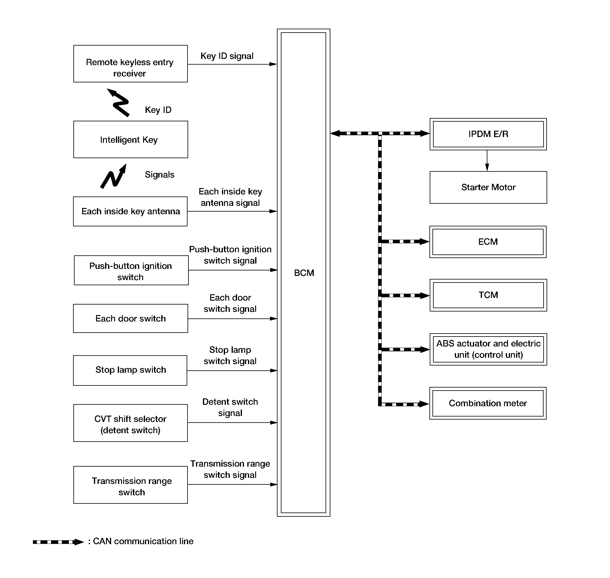
INPUT SIGNAL AND OUTPUT SIGNAL CHART
| Component | Signal description |
|---|---|
| ECM |
Mainly transmits the following signal to BCM and combination meter via CAN communication.
Mainly receives the following signal from BCM via CAN communication.
|
| IPDM E/R |
Mainly receives the following signal from BCM via CAN communication.
|
| ABS actuator and electric unit (control unit) |
Mainly transmits the following signal to BCM via CAN communication.
|
| Combination meter |
Mainly transmits the following signal to BCM, ECM and IPDM E/R via CAN communication.
|
| TCM (Transmission Control Module) |
Mainly receives the following signal from BCM via CAN communication.
|
SYSTEM DESCRIPTION
-
The engine start function of Intelligent Key system makes it possible to start and stop the engine without using the key, based on the electronic ID verification. The electronic ID verification is performed between BCM and Intelligent Key when the push-button ignition switch is pressed, while the Intelligent Key is within the detection area of inside key antenna.
 NOTE:
NOTE:
The driver should carry the Intelligent Key at all times.
-
Intelligent Key has 2 IDs [Intelligent Key ID and IVIS (NATS) ID]. It can perform the door lock/unlock operation and the push-button ignition switch operation when the registered Intelligent Key is carried.
-
When Intelligent Key battery is discharged, engine can be started by operating push-button ignition switch after contacting Intelligent Key backside to push-button ignition switch. At that time, the IVIS (NATS) ID verification is performed.
-
If the ID is successfully verified, when push-button ignition switch is pressed, the engine can be started.
-
Up to 4 Intelligent Keys can be registered (Including the standard Intelligent Key) upon request from the customer.
-
For initialization and registration of Intelligent Keys, refer to CONSULT Immobilizer mode and follow the on-screen instructions.
NOTE:
Refer to System Description for any functions other than engine start function of Intelligent Key system.
PRECAUTIONS FOR INTELLIGENT KEY SYSTEM
The transponder [the chip for IVIS (NATS) ID verification] is integrated into the Intelligent Key.
In that case, the IVIS (NATS) ID verification can be performed when Intelligent Key backside is contacted to push-button ignition switch. If verification result is OK, engine can be started.
OPERATION WHEN INTELLIGENT KEY IS CARRIED
-
When the push-button ignition switch is pressed, the BCM activates the inside key antenna and transmits the request signal to the Intelligent Key.
-
The Intelligent Key receives the request signal and transmits the Intelligent Key ID signal to the BCM.
-
BCM receives the Intelligent Key ID signal via remote keyless entry receiver and verifies it with the registered ID.
-
BCM turns accessory relay-1 ON and transmits the ignition power supply ON signal to IPDM E/R.
-
IPDM E/R turns the ignition relay-1 ON and starts the ignition power supply.
-
BCM detects the selector lever position and brake pedal operating condition.
-
BCM transmits the starter request signal to IPDM E/R and turns the starter relay in IPDM E/R ON, if BCM judges that the engine start condition* is satisfied.
-
IPDM E/R turns the starter control relay ON when receiving the starter request signal.
-
Power supply is supplied through the starter relay and the starter control relay to operate the starter motor.
CAUTION:
If a malfunction is detected in the Intelligent Key system, the “KEY” warning lamp in the combination meter illuminates. At that time, the engine cannot be started.
-
When BCM receives feedback signal from ECM indicating that the engine is started, the BCM transmits a stop signal to IPDM E/R and stops cranking by turning OFF the starter relay (If engine start is unsuccessful, cranking stops automatically within 5 seconds).
CAUTION:
When the Intelligent Key is carried outside of the Nissan Murano vehicle (inside key antenna detection area) while the power supply is in the ACC or ON position, even if the engine start condition* is satisfied, the engine cannot be started.
*: For the engine start condition, refer to the table below “POWER SUPPLY POSITION CHANGE TABLE BY PUSH-BUTTON IGNITION SWITCH OPERATION”.
OPERATION RANGE
Engine can be started when Intelligent Key is inside the vehicle. However, sometimes engine may not start when Intelligent Key is on instrument panel or in glove box.
ENGINE START OPERATION WHEN INTELLIGENT KEY IS CONTACTED TO PUSH-BUTTON IGNITION SWITCH
When Intelligent Key battery is discharged, the IVIS (NATS) ID verification between transponder in Intelligent Key and BCM is performed when Intelligent Key backside is contacted to push-button ignition switch. If the verification result is OK, engine can be started.
POWER SUPPLY POSITION CHANGE TABLE BY PUSH-BUTTON IGNITION SWITCH OPERATION
The power supply position changing operation can be performed with the following operations.
NOTE:
-
When an Intelligent Key is within the detection area of inside key antenna and when Intelligent Key backside is contacted to push-button ignition switch, it is equivalent to the operations below.
-
When starting the engine, the BCM monitors under the engine start conditions:
-
Brake pedal operating condition
-
Selector lever position
-
Nissan Murano Vehicle speed
-
Vehicle speed: less than 2.5 MPH (4 km/h)
| Power supply position | Engine start/stop condition | Push-button ignition switch operation frequency | |
|---|---|---|---|
| Selector lever | Brake pedal operation condition | ||
| LOCK → ACC | — | Not depressed | 1 |
| LOCK → ACC → ON | — | Not depressed | 2 |
| LOCK → ACC → ON → OFF | — | Not depressed | 3 |
|
LOCK → START ACC → START ON → START |
P or N position | Depressed | 1 |
| Engine is running → OFF | — | — | 1 |
Vehicle speed: 2.5 MPH (4 km/h)
| Power supply position | Engine start/stop condition | Push-button ignition switch operation frequency | |
|---|---|---|---|
| Selector lever | Brake pedal operation condition | ||
| Engine is running → ACC | — | — | Emergency stop operation |
| Engine stall return operation while driving | N position | Not depressed | 1 |
Emergency stop operation
-
Press and hold the push-button ignition switch for 2 seconds or more.
-
Press the push-button ignition switch 3 times or more within 1.5 seconds.
 System
..
 Nissan Vehicle Immobilizer System-Nats
System Description
SYSTEM DIAGRAMINPUT SIGNAL AND OUTPUT SIGNAL CHART Component Signal description
ECM
Mainly transmits the following signal to BCM and combination meter via CAN communication...
Other information:
Nissan Murano (Z52) 2015-2024 Owners Manual: Engine cooling system
The engine cooling system is filled at the factory with a pre-diluted mixture of 50% Genuine NISSAN Long Life Antifreeze/Coolant (blue) and 50% water to provide year-round antifreeze and coolant protection. The antifreeze solution contains rust and corrosion inhibitors...
Nissan Murano (Z52) 2015-2024 Owners Manual: Larger children
Children should remain in a forward-facing child restraint with a harness until they reach the maximum height or weight limit allowed by the child restraint manufacturer. Once a child outgrows the height or weight limit of the harness-equipped forwardfacing child restraint, NISSAN recommends that the child be placed in a commercially available booster seat to obtain proper seat belt fit...
Categories
- Manuals Home
- Nissan Murano Owners Manual
- Nissan Murano Service Manual
- Indicator lights
- Memory storage function (key-link)
- System malfunction
- New on site
- Most important about car
Seatback pockets

Theremaybe one or two seatback pockets located on the back of the driver and passenger seats. The pockets can be used to store maps.
WARNING