
Nissan Murano: Roof :: Removal and Installation / Moonroof Motor Assembly
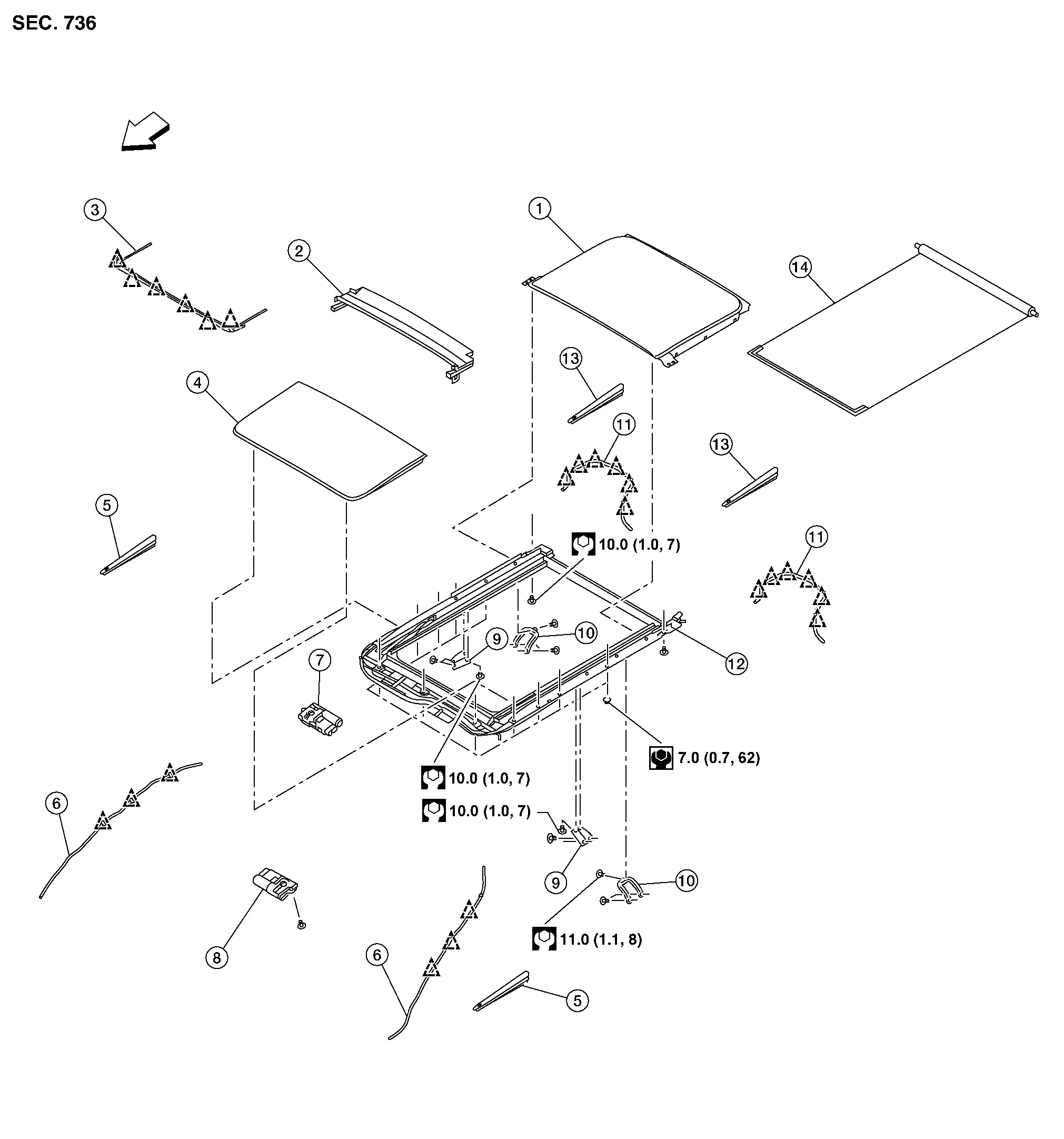
| 1. | Panoramic roof glass | 2. | Moonroof drain | 3. | Wind deflector |
| 4. | Glass lid | 5. | Side trim covers (LH/RH) | 6. | Front drain hose (LH/RH) |
| 7. | Moonroof motor assembly | 8. | Sunshade motor assembly | 9. | Moonroof front bracket (LH/RH) |
| 10. | Moonroof rear bracket (LH/RH) | 11. | Rear drain hose (LH/RH) | 12. | Moonroof unit assembly |
| 13. | Rear trim covers (LH/RH) | 14. | Sunshade |  |
Front |
 |
Pawl |  |
Clip |
REMOVAL
Close glass lid.
Remove the headlining. Refer to Removal and Installation.
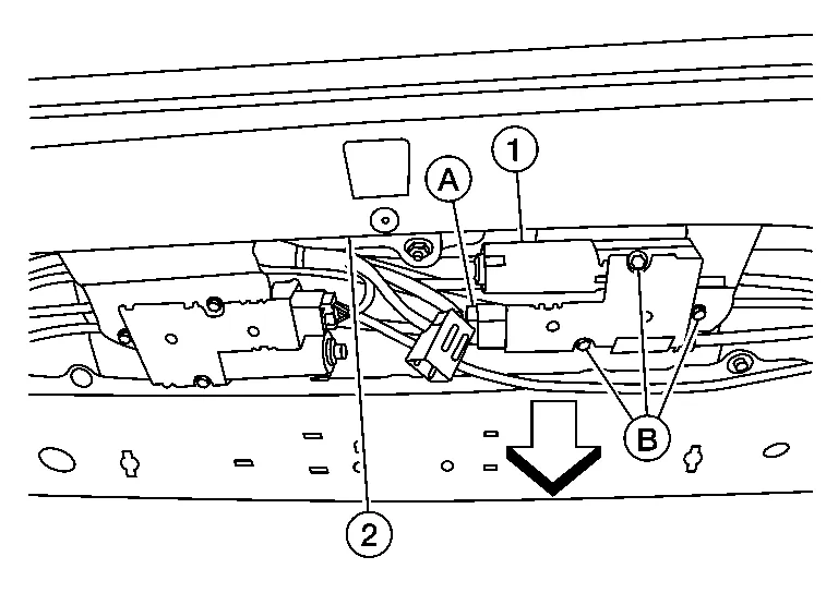
Disconnect harness connector (A) from moonroof motor assembly (1).
CAUTION:
Do not run the removed moonroof motor assembly as a single unit.
Remove moonroof motor assembly screws (B) and release from moonroof unit assembly (2)
: Front
INSTALLATION
Move moonroof motor assembly laterally little by little so that the gear is completely engaged into the wire on the moonroof unit assembly, and the mounting surfaces become parallel. Install the moonroof motor assembly screws and tighten.
CAUTION:
Before installing the moonroof motor unit, be sure to place the link and wire assembly in the symmetrical and fully closed position.
 NOTE:
NOTE:
If necessary, insert a suitable tool into the drive key and rotate right or left slightly to assist in complete moonroof motor gear alignment.
Remainder of installation is in the reverse order of removal.
CAUTION:
When replacing moonroof motor unit, be sure to perform “ADDITIONAL SERVICE WHEN REPLACING CONTROL UNIT”. Refer to Special Repair Requirement.
 Glass Lid
Exploded View
1.
Panoramic roof glass
2.
Moonroof drain
3.
Wind deflector
4.
Glass lid
5.
Side trim covers (LH/RH)
6.
Front drain hose (LH/RH)
7...
 Moonroof Unit Assembly
Inspection
WIND DEFLECTOROpen glass lid fully.
Visually check for proper installation, damaged/deteriorated components, or foreign objects within mechanism...
Other information:
Nissan Murano (Z52) 2015-2024 Service Manual: U1232 Steering Angle Sensor
DTC Description DTC DETECTION LOGIC DTC No. CONSULT screen terms (Trouble diagnosis content) DTC detection condition U1232 ST ANGLE SEN CALIB (Steering angle sensor calibration) Diagnosis condition When ignition switch is ON Signal (terminal) — Threshold — Diagnosis delay time — POSSIBLE CAUSE Neutral position adjustment of the steering angle sensor is incomplete Steering angle sensor FAIL-SAFEPredictive course line is not displayed DTC Confirmation Procedure PERFORM DTC CONFIRMATION PROCEDURE CONSULT Ignition switch ON...
Nissan Murano (Z52) 2015-2024 Service Manual: B2614 Bcm
DTC Description DTC DETECTION LOGIC DTC No. CONSULT screen items (Trouble diagnosis content) DTC Detection Condition B2614 BCM (Body control module) Diagnosis condition Always Signal (terminal) Accessory relay-1 control Threshold The following states are compared, and they do not match for 1 second or more: State of accessory relay-1 control judged by BCM State of accessory relay-1 control signal Diagnosis delay time 1 second or more...
Categories
- Manuals Home
- Nissan Murano Owners Manual
- Nissan Murano Service Manual
- Tire rotation
- Indicator lights
- Intelligent Forward Collision Warning (I-FCW)
- New on site
- Most important about car
