Nissan Murano: Dtc/circuit Diagnosis / Its Can Communication Circuit
CHECK CAN DIAGNOSIS
Check the CAN diagnosis results from CONSULT to see that the Nissan Murano vehicle CAN communication circuit has no malfunction.
Are the vehicle CAN communication circuits normal?
YES>>GO TO 2.
NO>>Check and repair Nissan Murano vehicle CAN communication circuit.
CONNECTOR INSPECTION
-
Turn the ignition switch OFF.
-
Disconnect the battery cable from the negative terminal.
-
Check the terminals and connectors of the ADAS control unit for damage, bend and loose connection (unit side and connector side).
Is the inspection result normal?
YES>>GO TO 3.
NO>>Repair the terminal and connector.
CHECK HARNESS CONTINUITY (OPEN CIRCUIT)
-
Disconnect the ADAS control unit harness connector.
-
Check the continuity between the ADAS control unit harness connector terminals.
ADAS control unit harness connector Continuity Connector No. Terminal No. M182 15 20 Existed 3 19 Existed
Is the inspection result normal?
YES>>GO TO 4.
NO>>Repair the ADAS control unit branch line. (ITS CAN communication circuit side).
CHECK HARNESS CONTINUITY (SHORT CIRCUIT)
-
Disconnect all the unit connector on ITS CAN communication system.
-
Check the continuity between the ADAS control unit harness connector terminals.
ADAS control unit harness connector Continuity Connector No. Terminal No. M182 15 3 Not existed
Is the inspection result normal?
YES>>GO TO 5.
NO>>Check the harness and repair the root cause.
CHECK HARNESS CONTINUITY (SHORT CIRCUIT)
Check the continuity between the ADAS control unit harness connector and the ground.
| ADAS control unit harness connector | Ground | Continuity | |
| Connector No. | Terminal No. | ||
| M182 | 15 | Not existed | |
| 3 | Not existed | ||
Is the inspection result normal?
YES>>GO TO 6.
NO>>Check the harness and repair the root cause.
CHECK TERMINATION CIRCUIT
-
Remove the ADAS control unit.
-
Check the resistance between the ADAS control unit terminals.
ADAS control unit Resistance (Ω) Terminal No. 15 3 Approx. 108 – 132 20 19 Approx. 108 – 132
Is the inspection result normal?
YES>>GO TO 7.
NO>>Replace the ADAS control unit.
CHECK SYMPTOM
Connect all the connectors. Check if the symptoms described in the “Symptom (Results from interview with customer)” are reproduced.
Inspection result
Reproduced>>GO TO 8.
NO>>Start the diagnosis again. Follow the trouble diagnosis procedure when past error is detected.
CHECK UNIT REPRODUCTION
Perform the reproduction test as per the following procedure for each unit.
-
Turn the ignition switch OFF.
-
Disconnect the battery cable from the negative terminal.
-
Disconnect one of the unit connectors of ITS CAN communication circuit.
 NOTE:
ADAS control unit has two termination circuits. Check other units first.
-
Connect the battery cable to the negative terminal. Check if the symptoms described in the “Symptom (Results from interview with customer)” are reproduced.
NOTE:
Although unit-related error symptoms occur, do not confuse them with other symptoms.
Inspection result
Reproduced>>Connect the connector. Check other units as per the above procedure.
NO>>Replace the unit whose connector was disconnected.
 Diagnostic Can Communication Circuit
Diagnosis Procedure
CONNECTOR INSPECTION
Turn the ignition switch OFF.
Disconnect the battery cable from the negative terminal.
Check the following terminals and connectors for damage, bend and loose connection (unit side and connector side)...
 Chassis Can Communication Circuit
Diagnosis Procedure
CHECK CAN DIAGNOSIS
Check the CAN diagnosis results from CONSULT to see that the Nissan Murano vehicle CAN communication circuit and ITS CAN communication circuit have no malfunction...
Other information:
Nissan Murano (Z52) 2015-2024 Service Manual: C1a18 Radar Aiming Incmp
DTC Description DTC DETECTION LOGIC DTC No. CONSULT screen terms DTC detection condition C1A18–54 LASER AIMING INCMP Diagnosis condition When Ignition switch is ON. Signal (terminal) — Threshold The radar of the distance sensor (ICC sensor) is not adjusted Diagnosis delay time — POSSIBLE CAUSE The adjustment of the radar is not yet performed Interruption in radar adjustment FAIL-SAFEThe following systems are canceled: Intelligent Cruise Control Automatic Emergency Braking (AEB) Intelligent Forward Collision Warning (I-FCW) DTC Confirmation Procedure PERFORM DTC CONFIRMATION PROCEDURE CONSULT Start the engine...
Nissan Murano (Z52) 2015-2024 Service Manual: I-Li
System Description SYSTEM DIAGRAMADAS CONTROL UNIT INPUT/OUTPUT SIGNAL ITEMInput Signal Item Transmit unit Signal name Description ECM CAN communication Brake pedal position switch signal Receives Brake pedal position switch state Accelerator pedal position signal Receives accelerator pedal position (angle) Stop lamp switch signal Receives stop lamp switch state Engine speed signal Receives engine speed TCM CAN communication Input speed signal Receives the number of revolutions of input shaft Current gear position signal Receives a current gear position Shift position signal Receives a selector lever position Output shaft revolution signal Receives the number of revolutions of output shaft ABS actuator and electric unit (control unit) CAN communication ABS malfunction signal Receives a malfunction state of ABS ABS operation signal Receives an operational state of ABS TCS malfunction signal Receives a malfunction state of TCS TCS operation signal Receives an operational state of TCS VDC OFF switch signal Receives an ON/OFF state of VDC VDC malfunction signal Receives a malfunction state of VDC VDC operation signal Receives an operational state of VDC Nissan Murano Vehicle speed signal (ABS) Receives wheel speeds of four wheels Yaw rate signal Receives yaw rate acting on the Nissan Murano vehicle Side G sensor signal Receives lateral G acting on the Nissan Murano vehicle Combination meter CAN communication Parking brake switch signal Receives an operational state of the parking brake System selection signal Receives a selection state of each item in "Driver Assistance" BCM CAN communication Turn indicator signal Receives an operational state of the turn signal lamp and the hazard lamp Steering angle sensor CAN communication Steering angle sensor malfunction signal Receives a malfunction state of steering angle sensor Steering angle sensor signal Receives the number of revolutions, turning direction of the steering wheel Steering angle speed signal Receives the turning angle speed of the steering wheel Lane intervention switch Lane intervention switch signal Receives an ON/OFF state of the lane intervention switch Lane camera unit ITS communication Detected lane condition signal Receives detection results of lane marker Output Signal Item Reception unit Signal name Description ABS actuator and electric unit (control unit) CAN communication Target yaw moment signal Transmits a target yaw moment signal to generate yaw moment to the Nissan Murano vehicle Combination meter CAN communication Intelligent Lane Intervention ON indicator lamp signal Transmits an Intelligent Lane Intervention ON indicator lamp signal to turn ON the Intelligent Lane Intervention ON indicator lamp Lane departure warning lamp signal Transmits an lane departure warning lamp signal to turn ON the lane departure warning lamp Lane camera unit ITS communication Nissan Murano Vehicle speed signal Transmits a vehicle speed calculated by the ADAS control unit Turn indicator signal Transmits a turn indicator signal received from BCM Steering assist system ON indicator Steering assist system ON indicator signal Turns ON the steering assist system ON indicator Intelligent Lane Intervention system ON indicator Intelligent Lane Intervention system ON indicator signal Turns ON the Intelligent Lane Intervention system ON indicator Warning system buzzer Warning buzzer signal Activates warning system buzzer...
Categories
- Manuals Home
- Nissan Murano Owners Manual
- Nissan Murano Service Manual
- Passenger compartment
- Fuel recommendation
- High Beam Assist (if so equipped)
- New on site
- Most important about car
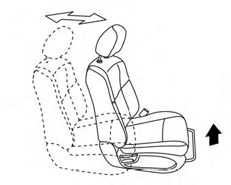
Front manual seat adjustment (if so equipped)
Your vehicle seats can be adjusted manually. For additional information about adjusting the seats, refer to the steps outlined in this section.
Forward and backward