
Nissan Murano: Door & Lock :: Dtc/circuit Diagnosis / Intelligent Key
 NOTE:
NOTE:
The Signal Tech II Tool [- (J-50190)] can be used to perform the following functions: Refer to the Signal Tech II User Guide for additional information.
-
Check Intelligent Key relative signal strength.
-
Confirm Nissan Murano vehicle Intelligent Key antenna signal strength.
CHECK FUNCTION
 CONSULT
-
Select “RKE OPE COUN1” in “Data Monitor” mode of “BCM(INTELLIGENT KEY)”.
-
Check that the function operates normally according to the following conditions:
| Monitor Item | Condition |
|---|---|
| RKE OPE COUN1 | Check that the numerical value is changing while operating the Intelligent Key. |
Is the inspection result normal?
YES>>Intelligent Key is OK.
NO>>Refer to Diagnosis Procedure.
NOTE:
The Signal Tech II Tool [- (J-50190)] can be used to perform the following functions. Refer to the Signal Tech II User Guide for additional information.
-
Check Intelligent Key relative signal strength.
-
Confirm Nissan Murano vehicle Intelligent Key antenna signal strength.
CHECK INTELLIGENT KEY FUNCTION
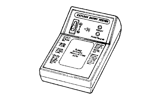
Check Intelligent Key function using Signal Tech II Tool [- (J-50190)] or Remote Keyless Entry Tester [- (J-43241)] (shown).
Does the test pass?
YES>>Intelligent Key is OK.
NO>>GO TO 2.
CHECK INTELLIGENT KEY COMPONENTS
-
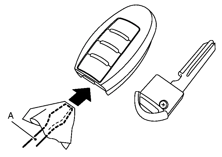
Release the lock knob at the back of the Intelligent Key and remove the mechanical key.
-
Insert a flat-blade screwdriver (A) wrapped with a cloth into the slit of the corner and twist it to separate the upper part from the lower part.
CAUTION:
-
Do not touch the circuit board or battery terminal.
-
The Intelligent Key is water-resistant. However, if it does get wet, immediately wipe it dry.
-
-
Remove the Intelligent Key battery.
CAUTION:
-
Keep dirt, grease, and other foreign materials off the electrode contact area.
-
-
Visually inspect Intelligent Key internal components.
Is the inspection result normal?
YES>>GO TO 3.
NO>>Repair or replace malfunctioning parts.
CHECK INTELLIGENT KEY BATTERY
Check by connecting a resistance (approximately 300Ω) so that the current value becomes about 10 mA.
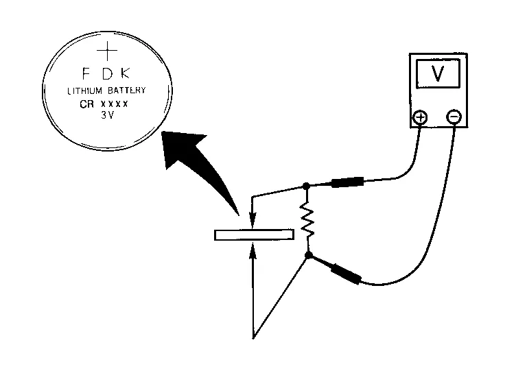
| Standard | : Approx. 2.5 - 3.0V |
Is the measurement value within specification?
YES>>Intelligent Key battery is OK. Check remote keyless entry receiver. Refer to Component Function Check.
NO>>GO TO 4.
REPLACE INTELLIGENT KEY BATTERY
-
Replace the Intelligent Key battery.
-
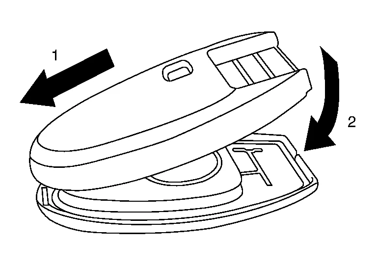
Align the tips of the upper and lower parts, and then push them together until it is securely closed.
CAUTION:
-
When replacing battery, keep dirt, grease, and other foreign materials off the electrode contact area.
-
-
After replacing the battery, check that all Intelligent Key functions work properly.
Is the inspection result normal?
YES>>Intelligent Key is OK.
NO>>Check remote keyless entry receiver. Refer to Component Function Check.
 Intelligent Key Warning Buzzer
Component Function Check
CHECK FUNCTION
CONSULT
Select “OUTSIDE BUZZER” in “Active Test” mode of “BCM(INTELLIGENT KEY)”.
Select “On” or “Off” to check that it works normally...
 Meter Buzzer Circuit
Description
The buzzer for the warning chime system is installed in the combination meter.
The combination meter sounds the buzzer based on the signals transmitted from various units...
Other information:
Nissan Murano (Z52) 2015-2024 Service Manual: Security Indicator Lamp
Component Function Check CHECK FUNCTION CONSULT Select the "THEFT IND" in "Active Test" mode of "BCM(IMMU)". Check security indicator lamp operation. Test item Description THEFT IND ON Security indicator lamp Illuminates OFF Does not illuminate Is the inspection result normal? YES>> Inspection End...
Nissan Murano (Z52) 2015-2024 Service Manual: Differential Side Oil Seal
Exploded View 1. Transaxle assembly 2. Differential side oil seal (left side) 3. Differential side oil seal (right side) (FWD models only) : Apply CVT fluid Removal and Installation REMOVALRemove front drive shaft...
Categories
- Manuals Home
- Nissan Murano Owners Manual
- Nissan Murano Service Manual
- Indicator lights
- Passenger compartment
- Rear bench seat adjustment
- New on site
- Most important about car
