Nissan Murano: General Information :: How to Use This Manual / How to Read Wiring Diagrams
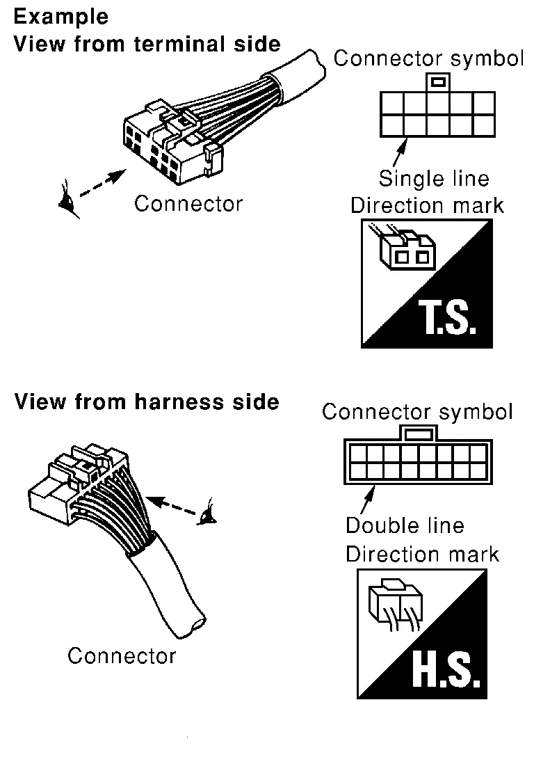
Most connector symbols in wiring diagrams are shown from the terminal side.
-
Connector symbols shown from the terminal side are enclosed by a single line and followed by the direction mark.
-
Connector symbols shown from the harness side are enclosed by a double line and followed by the direction mark.
-
Certain systems and components, especially those related to OBD, may use a new style slide-locking type harness connector. For description and how to disconnect, refer to PG section, “Description”, “HARNESS CONNECTOR”.
-
Male and female terminals
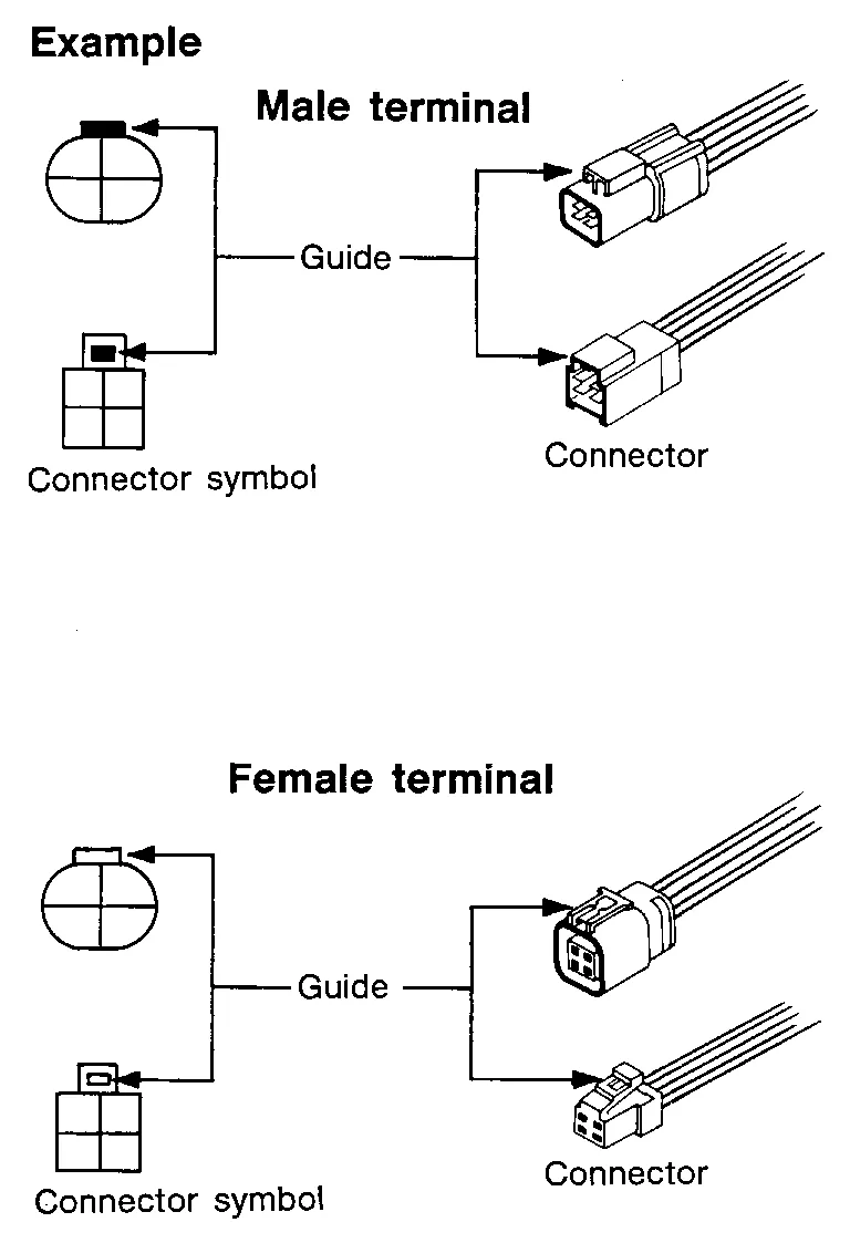
Connector guides for male terminals are shown in black and female terminals in white in wiring diagrams.
Each section includes wiring diagrams.
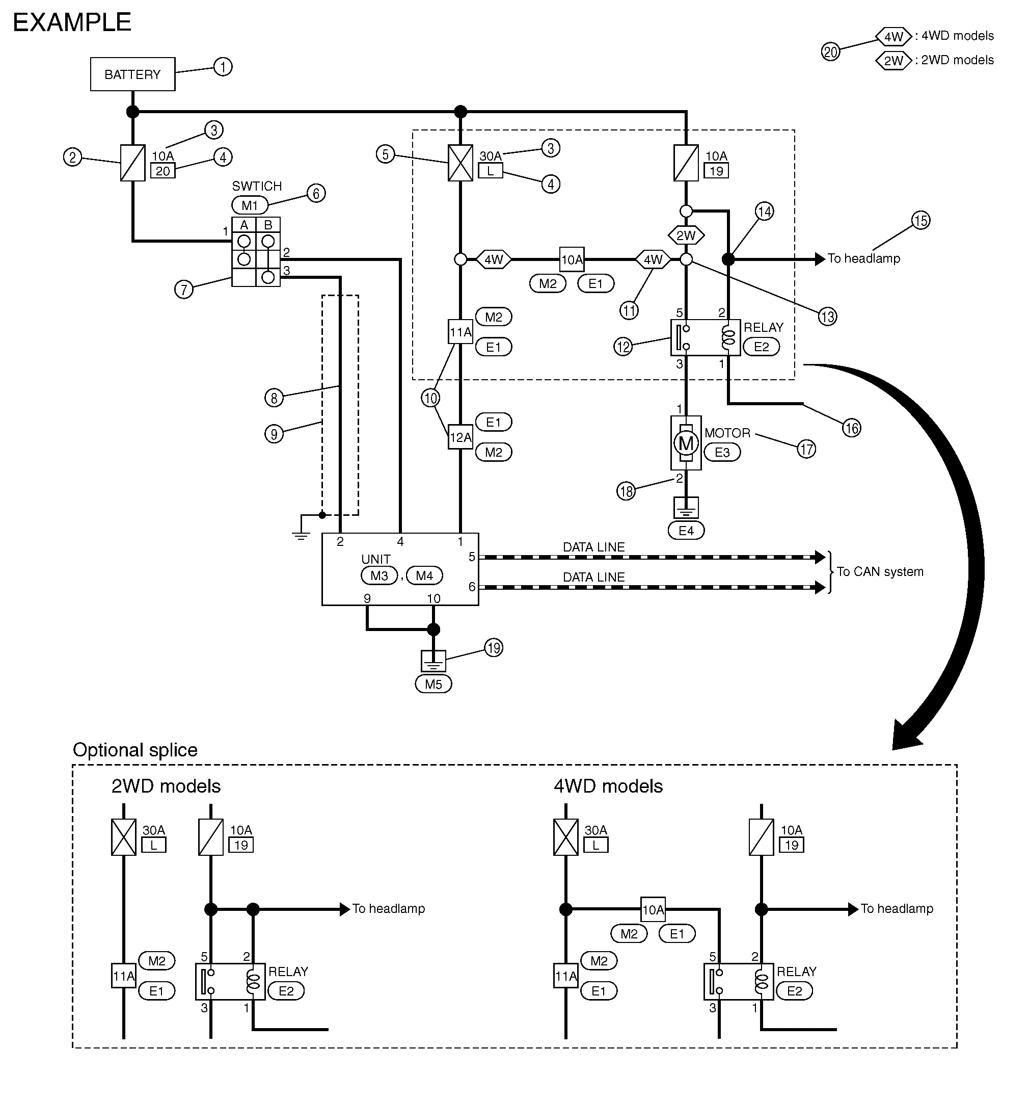
| No. | Item | Description | |
|---|---|---|---|
| 1 | Power supply |
|
|
| 2 | Fuse |
|
|
| 3 | Current rating of fusible link/fuse |
|
|
| 4 | Number of fusible link/fuse |
|
|
| 5 | Fusible link |
|
|
| 6 | Connector number |
|
|
| 7 | Switch |
|
|
| 8 | Circuit (Wiring) |
|
|
| 9 | Shielded line |
|
|
| 10 | Connectors |
|
|
| 11 | Option abbreviation |
|
|
| 12 | Relay |
|
|
| 13 | Optional splice |
|
|
| 14 | Splice |
|
|
| 15 | System branch |
|
|
| 16 | Page crossing |
|
|
| 17 | Component name |
|
|
| 18 | Terminal number |
|
|
| 19 | Ground (GND) |
|
|
| 20 | Explanation of option description |
|
|
 ”.
”. ” means the splice.
SWITCH POSITIONS
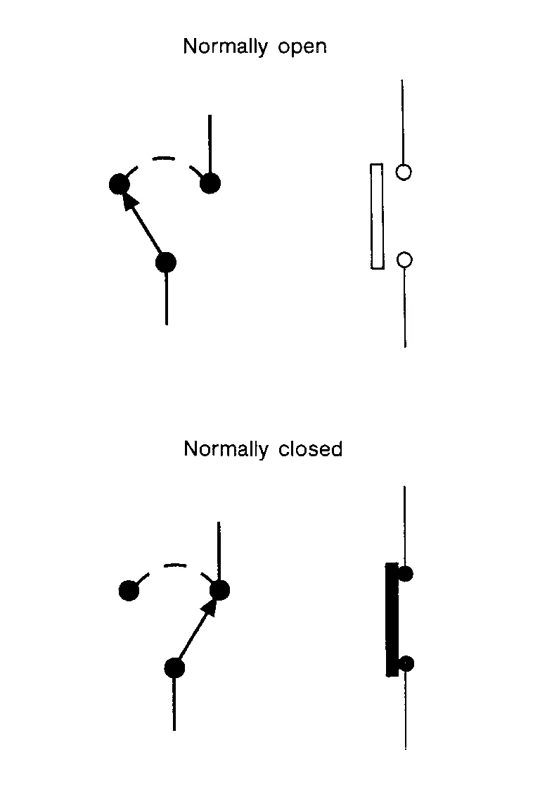
Switches are shown in wiring diagrams as if the vehicle is in the “normal” condition.
A vehicle is in the “normal” condition when:
-
Ignition switch OFF”.
-
Doors, hood and trunk lid/back door are closed
-
Pedals are not depressed
-
Parking brake is released
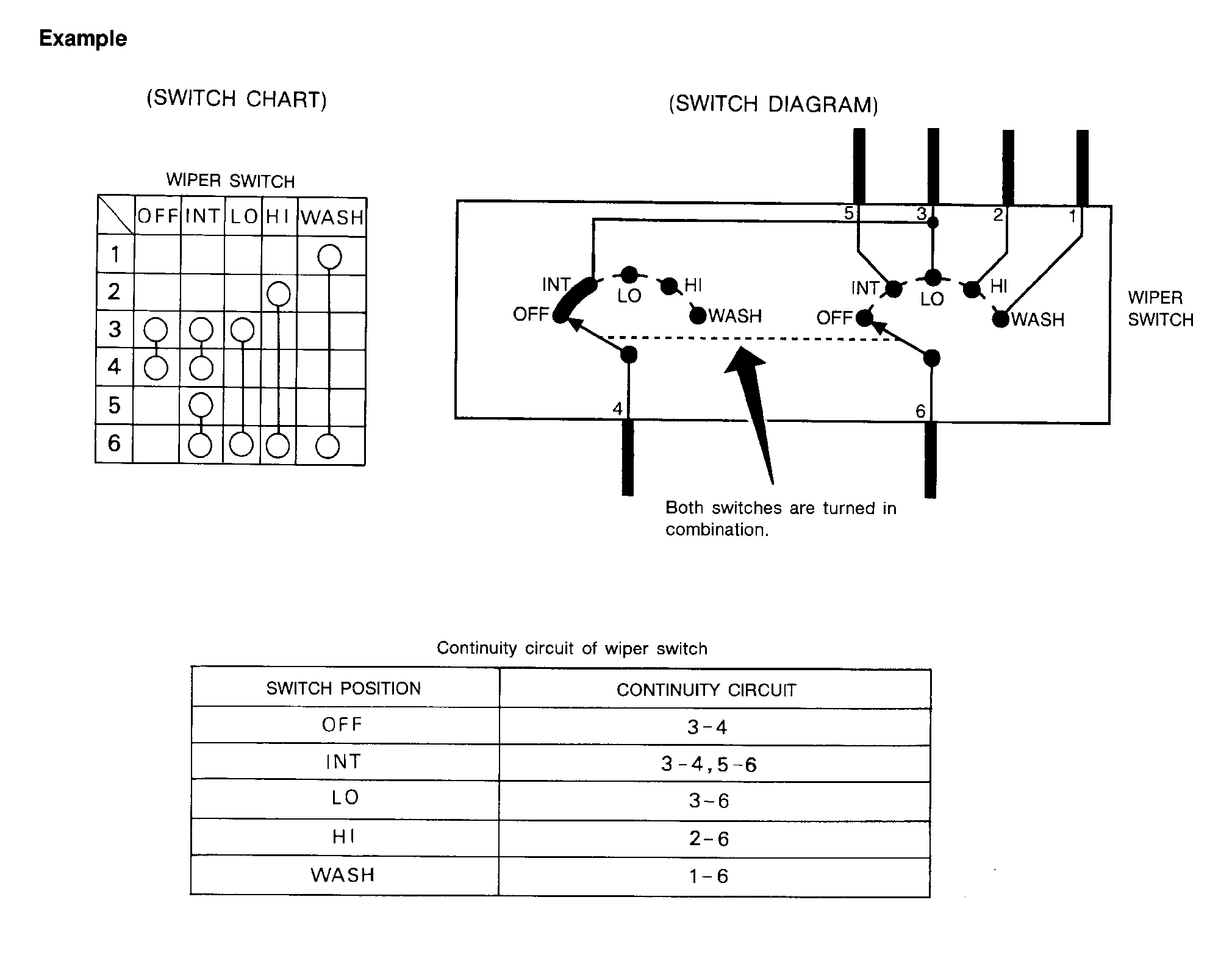
MULTIPLE SWITCH
The continuity of multiple switch is described in two ways as shown below.
-
The switch chart is used in schematic diagrams.
-
The switch diagram is used in wiring diagrams.
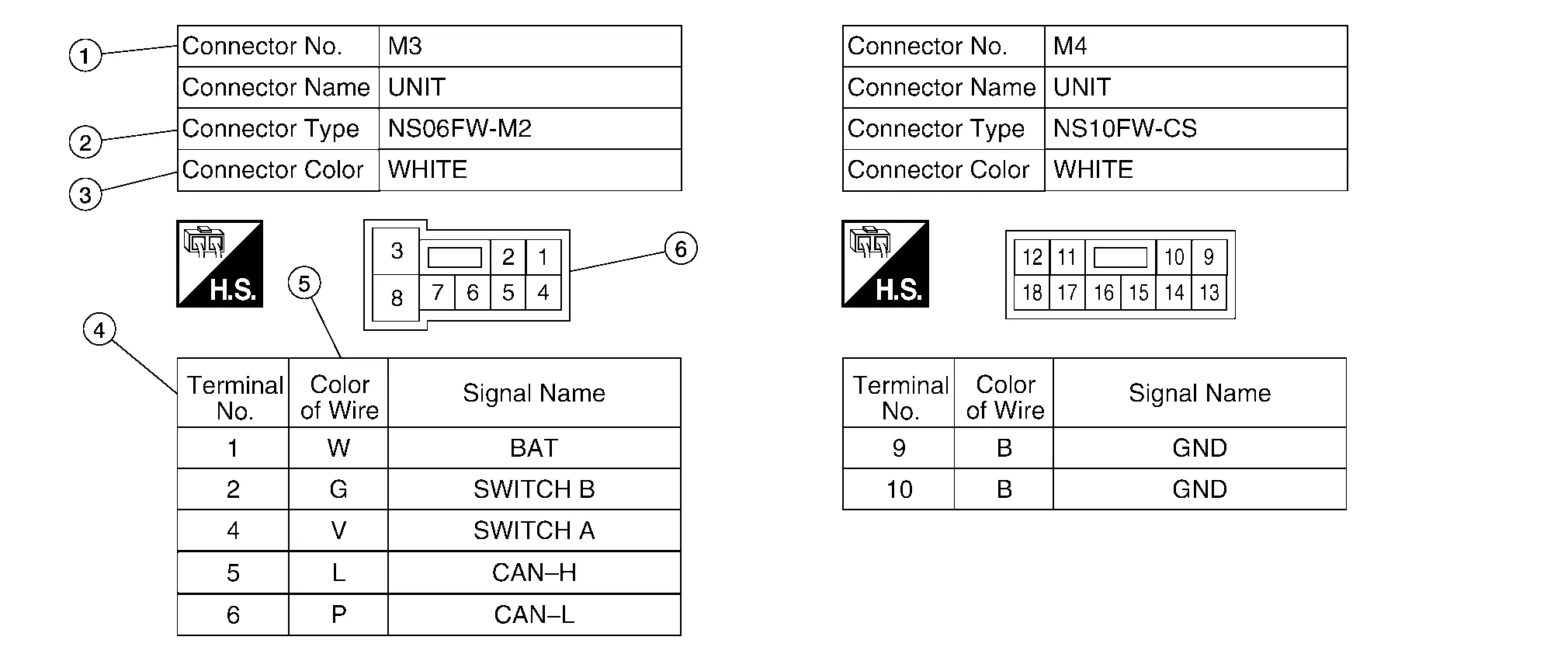
| No. | Item | Description | |
|---|---|---|---|
| 1 | Connector number |
|
|
| 2 | Connector type |
 : Special type : Special type |
|
| 3 | Connector color |
|
|
| 4 | Terminal number |
|
|
| 5 | Wire color |
|
|
|
B = Black W = White R = Red G = Green L = Blue Y = Yellow LG = Light Green BG or BE = Beige BR = Brown |
LA = Lavender OR or O = Orange P = Pink PU or V (Violet) = Purple GY or GR = Gray SB = Sky Blue CH = Dark Brown DG = Dark Green |
||
|
|||
| 6 | Connector |
|
|
 : Connector model
 : Cavity
 : Male (M) and female (F) terminals
 : Connector color
 How to Follow Trouble Diagnoses
Description
NOTE:
Trouble diagnoses indicate work procedures required to diagnose problems effectively. Observe the following instructions before diagnosing:
Before performing trouble diagnoses, read the “Work Flow” in each section...
 Abbreviations
Abbreviation List
The following ABBREVIATIONS are used:A ABBREVIATION DESCRIPTION
A/C
Air conditioner
Air conditioning
A/F sensor
Air fuel ratio sensor
A/T
Automatic transaxle/transmission
ABS
Anti-lock braking system
ACCS
Advance climate control system
ACL
Air cleaner
AEB
Automatic Emergency Braking
AP
Accelerator pedal
APP
Accelerator pedal position
ATF
Automatic transmission fluid
ATR
Active torque rod
AV
Audio visual
AVM
Around view monitor
AWD
All wheel drive
B ABBREVIATION DESCRIPTION
BARO
Barometric pressure
BCI
Backup collision intervention
BCM
Body control module
BLSD
Brake limited slip differential
BPP
Brake pedal position
BSI
Blind spot intervention
BSW
Blind spot warning
C ABBREVIATION DESCRIPTION
CGW
Can Gateway
CKP
Crankshaft position
CL
Closed loop
CMP
Camshaft position
CPP
Clutch pedal position
CTP
Closed throttle position
CVT
Continuously variable transaxle/transmission
D ABBREVIATION DESCRIPTION
D1
Drive range first gear
D2
Drive range second gear
D3
Drive range third gear
D4
Drive range fourth gear
DCA
Distance control assist
DDS
Downhill drive support
DFI
Direct fuel injection system
DLC
Data link connector
DTC
Diagnostic trouble code
E ABBREVIATION DESCRIPTION
E/T
Exhaust temperature
EBD
Electric brake force distribution
EC
Engine control
ECD
Electronic controlled deceleration
ECL
Engine coolant level
ECM
Engine control module
ECT
Engine coolant temperature
ECV
Electrical control valve
EEPROM
Electrically erasable programmable read only memory
EFT
Engine fuel temperature
EGR
Exhaust gas recirculation
EGRT
Exhaust gas recirculation temperature
EGT
Exhaust gas temperature
ELD
Electronic locking differential
EOP
Engine oil pressure
EP
Exhaust pressure
EPR
Exhaust pressure regulator
EPS
Electronically controlled power steering
Electronic power steering
ESP
Electronic stability program system
EVAP canister
Evaporative emission canister
EVSE
Electric Nissan Murano vehicle supply equipment
EXC
Exhaust control
F ABBREVIATION DESCRIPTION
FC
Fan control
FCW
Forward collision warning
FEB
Forward Emergency Braking
FIC
Fuel injector control
FP
Fuel pump
FR
Front
FRP
Fuel rail pressure
FRT
Fuel rail temperature
FTP
Fuel tank pressure
FTT
Fuel tank temperature
G ABBREVIATION DESCRIPTION
GND
Ground
GPS
Global positioning system
GST
Generic scan tool
H ABBREVIATION DESCRIPTION
HBMC
Hydraulic body-motion control system
HDD
Hard disk drive
HO2S
Heated oxygen sensor
HOC
Heated oxidation catalyst
HPCM
Hybrid powertrain control module
I ABBREVIATION DESCRIPTION
I/M
Inspection and maintenance
IA
Intake air
IAC
Idle air control
IAT
Intake air temperature
IBA
Intelligent brake assist
IC
Ignition control
ICC
Intelligent cruise control
ICM
Ignition control module
IPDM E/R
Intelligent power distribution module engine room
ISC
Idle speed control
ISS
Input shaft speed
ITS
Information technology suite
IVC
In-Nissan Murano vehicle communications
K ABBREVIATION DESCRIPTION
KS
Knock sensor
L ABBREVIATION DESCRIPTION
LBC
Li-ion battery controller
LCD
Liquid crystal display
LCU
Local control unit
LDP
Lane departure prevention
LDW
Lane departure warning
LED
Light emitting diode
LH
Left-hand
LHD
Left-hand drive
LIN
Local interconnect network
M ABBREVIATION DESCRIPTION
M/T
Manual transaxle/transmission
MAF
Mass airflow
MAP
Manifold absolute pressure
MDU
Multi display unit
MI
Malfunction indicator
MIL
Malfunction indicator lamp
MOD
Moving object detection
N ABBREVIATION DESCRIPTION
NOX
Nitrogen oxides
O ABBREVIATION DESCRIPTION
O2
Oxygen
O2S
Oxygen sensor
OBD
On board diagnostic
OC
Oxidation catalytic converter
OD
Overdrive
OL
Open loop
OSS
Output shaft speed
P ABBREVIATION DESCRIPTION
P/S
Power steering
PBR
Potentio balance resistor
PCV
Positive crankcase ventilation
PFCW
Predictive forward collision warning
PNP
Park/Neutral position
PSP
Power steering pressure
PTC
Positive temperature coefficient
PTO
Power takeoff
PWM
Pulse width modulation
R ABBREVIATION DESCRIPTION
RAM
Random access memory
RAS
Rear active steer
RH
Right-hand
RHD
Right-hand drive
ROM
Read only memory
RPM
Engine speed
RR
Rear
S ABBREVIATION DESCRIPTION
SAE
Society of Automotive Engineers, Inc...
Other information:
Nissan Murano (Z52) 2015-2024 Service Manual: Rear Shock Absorber
Exploded View 1. Rear shock absorber 2. Piston rod lock nut 3. Shock absorber insulator 4. Bound bumper Front Removal and Installation REMOVALRemove the rear wheel and tire using power tool. Refer to Removal and Installation...
Nissan Murano (Z52) 2015-2024 Owners Manual: Vehicle-to-vehicle distance control mode
In the vehicle-to-vehicle distance control mode, the ICC system automatically maintains a selected distance from the vehicle traveling in front of you according to that vehicle’s speed (up to the set speed), or at the set speed when the road ahead is clear...
Categories
- Manuals Home
- Nissan Murano Owners Manual
- Nissan Murano Service Manual
- Indicator lights
- Vehicle Dynamic Control (VDC) OFF switch
- High Beam Assist (if so equipped)
- New on site
- Most important about car
Fuel gauge

The gauge indicates the approximate fuel level in the tank.
The gauge may move slightly during braking, turning, acceleration, or going up or down hills.
The gauge needle returns to 0 (Empty) after the ignition switch is placed in the OFF position.