
Nissan Murano: Engine Assembly / Fwd

| 1. | Gusset | 2. | Rear torque rod | 3. | Rear torque rod bracket |
| 4. | Upper torque rod | 5. | Engine mounting insulator (RH) | 6. | Engine mounting bracket (RH) |
| 7. | Engine mounting insulator (front) | 8. | Engine mounting bracket (front) | 9. | Vacuum hose |
| 10. | Vacuum tube (front) | 11. | Vacuum hose | 12. | Engine mounting insulator (LH) |
| 13. | Engine mounting insulator (rear) | 14. | Engine mounting bracket (rear) | 15. | Engine mounting stay (rear) |
| A. | To electronic controlled engine mount control solenoid valve. Refer to Exploded View. | B. | To transmission. Refer to Exploded View. |  |
Front |
WARNING:
-
Situate the vehicle on a flat and solid surface.
-
Place chocks at front and back of rear wheels.
-
For engines not equipped with engine slingers, attach proper slingers and bolts described in PARTS CATALOG.
CAUTION:
-
Always work safely.
-
Do not start work until the engine and exhaust system are cooled completely.
-
Refer to the applicable sections for warnings, cautions, notes, and instructions if necessary procedures are not included in the engine section.
-
For supporting, lifting and jacking points, refer to Garage Jack and Safety Stand and 2-Pole Lift.
-
Always use the support point specified for lifting.
-
Support the Nissan Murano vehicle at the rear axle jacking point with transmission jack or similar tool before removing the engine in preparation for the backward shift of the center of gravity.
 NOTE:
NOTE:
When removing components such as hoses, tubes/lines, etc., cap or plug openings to prevent fluid from spilling.
REMOVAL
Outline
Remove the engine and transmission with the front suspension member as a unit. Separate the engine from the transmission and remove from the front suspension member.
Preparation
Release fuel pressure. Refer to Work Procedure.
Drain engine coolant. Refer to Changing Engine Coolant.
CAUTION:
-
Perform this step when the engine is cold.
-
Do not allow the engine coolant to contact the drive belts.
Remove the front under cover. Refer to Removal and Installation.
Remove the front wheels and tires using power tool. Refer to Removal and Installation.
Remove the fender protector (LH/RH), Refer to Removal and Installation.
Engine Room
Remove cowl top and cowl top extension. Refer to Exploded View.
Remove the air duct (inlet), air cleaner cases (upper and lower) with mass air flow sensor and air duct assembly. Refer to Exploded View.
Remove the engine room cover. Refer to Removal and Installation.
Drain the power steering fluid. Refer to Draining and Refilling.
Disconnect engine room harness at the CVT and ECM connectors.
CAUTION:
Protect the harness connector with plastic bags or suitable covering to help prevent damage and intrusion of foreign materials into the connectors.
Remove the battery tray. Refer to Removal and Installation.
Disconnect heater hoses (engine side). Refer to Removal and Installation.
Remove upper and lower radiator hoses. Refer to Exploded View.
Remove high pressure pipe, low pressure pipe, high pressure flexible hose, and low pressure flexible hose. Refer to Exploded View.
Remove EVAP hose.
Disconnect fuel feed hose quick connector at fuel tube side. Refer to Exploded View.
Disconnect CVT control cable. Refer to Exploded View.
Disconnect brake booster vacuum hose at brake booster. Refer to Exploded View.
Remove harness ground cable.
Disconnect low pressure hose from steering pump. Refer to Removal and Installation.
Disconnect high pressure piping from steering pump. Refer to Removal and Installation.
Disconnect the wiring harness from the distribution/fuse block.
Disconnect the CVT fluid cooler hoses from the CVT.
Remove the upper RH upper torque rod.
Remove engine mounting insulator (RH) three upper nuts.
Vehicle Underbody
Remove exhaust front tube. Refer to Exploded View.
Disconnect steering lower joint at power steering gear assembly and release steering lower shaft. Refer to Exploded View.
Disconnect front stabilizer connecting rod. Refer to Exploded View.
Remove front brake caliper assembles with piping connected and position them aside. Refer to Removal and Installation.
Remove rear plate cover from oil pan (upper). Then remove nuts attaching the drive plate to the torque converter. Refer to Dowel Pin Alignment.
Remove crankshaft position sensor (POS). Refer to Exploded View.
CAUTION:
-
Handle carefully to avoid dropping and shocks.
-
Do not disassemble.
-
Do not allow metal powder to adhere to magnetic part at sensor tip.
-
Do not place sensors in a location where they are exposed to magnetism.
Removal
Use suitable tool to securely support bottom of front suspension member.
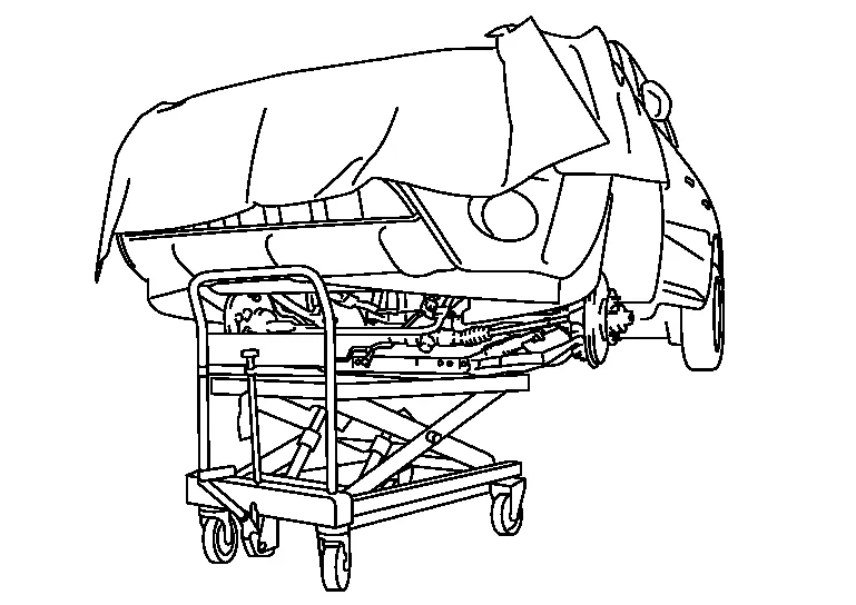
CAUTION:
Put a piece of wood or something similar as the supporting surface to secure a completely stable condition.
Remove front suspension member mounting nuts and bolts. Refer to Exploded View.
Carefully lower table to remove the engine, the transmission and the front suspension member. When performing work, observe the following caution:
CAUTION:
-
Confirm there is no interference with the Nissan Murano vehicle.
-
Repeatedly check to ensure all harnesses are disconnected before and during engine removal.
-
Check all connection points have been disconnected.
-
Keep in mind the center of Nissan Murano vehicle gravity changes. If necessary, use jack(s) to support the vehicle at rear jacking point(s) to prevent it from falling off the lift.
Separation
Install engine slingers into front of cylinder head (bank 1) and rear of cylinder head (bank 2).
-
Type 1
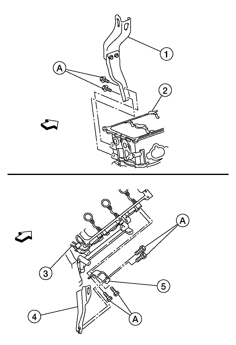
| (1) | : Engine rear slinger |
| (2) | : cylinder head (bank 2) |
| (3) | : cylinder head (bank 1) |
| (4) | : Engine front slinger (upper) |
| (5) | : Engine front slinger (lower) |
|
: Engine front |
| Bolts (A) | : 28.0 N·m (2.9 kg-m, 21 ft-lb) |
-
Type 2
(A): Cylinder head (bank 1)
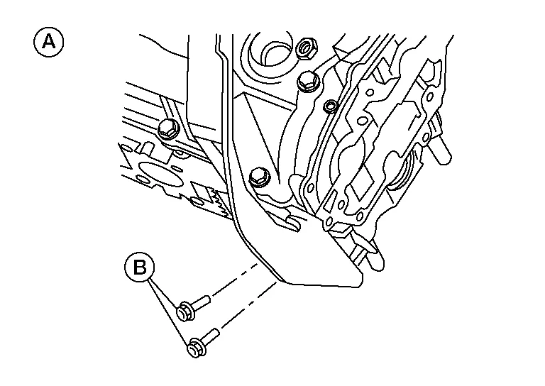
| Bolts (B) | : 28.0 N·m (2.9 kg-m, 21ft-lb) |
(B): Cylinder head (bank 2)

| Bolts (A) | : 28.0 N·m (2.9 kg-m, 21ft-lb) |
Disconnect vacuum hose from front engine mounting insulator.
Remove CVT fluid level indicator and CVT charging pipe. Refer to Exploded View.
Remove starter. Refer to Removal and Installation.
Remove front drive shaft (LH/RH). Refer to Removal and Installation (LH) and Removal and Installation (RH).
Remove coolant reservoir.
Remove engine mounting insulator (rear).
Disconnect CVT unit harness connector from CVT.
Remove transmission to engine bolts. Refer to Exploded View.
Separate engine and transmission assembly. Refer to Removal and Installation.
Lift the engine from the front suspension member.
CAUTION:
-
Repeatedly check to ensure all harnesses are disconnected before and during engine lifting.
-
Avoid spilling engine oil or grease onto the engine mounting insulators to prevent damage to engine mounting insulators.
INSTALLATION
Installation is in the reverse order of removal.
CAUTION:
-
Do not damage the engine mounting insulator. Do not spill engine oil on the engine mounting insulator.
-
Check all mounting insulators are seated properly, then tighten nuts and bolts.
INSPECTION AFTER INSTALLATION
-
Before starting engine, check oil/fluid levels including engine coolant and engine oil. If there is less than required quantity, fill to the specified level. Refer to Fluids and Lubricants.
-
Use procedure below to check for fuel leakage.
-
Turn ignition switch ON (with engine stopped). With fuel pressure applied to fuel piping, check for fuel leakage at connection points.
-
Start engine. With engine speed increased, check again for fuel leakage at connection points.
-
Run engine to check for unusual noise and vibration.
NOTE:
If hydraulic pressure inside timing chain tensioner drops after removal and installation, slack in the guide may generate a pounding noise during and just after engine start. However, this is normal. Noise will stop after hydraulic pressure rises.
-
Warm up engine thoroughly to make sure there is no leakage of fuel, exhaust gas, or any oils/fluids including engine oil and engine coolant.
-
Bleed air from passages in lines and hoses, such as in cooling system.
-
After cooling down engine, again check oil/fluid levels including engine oil and engine coolant. Refill to specified level, if necessary.
-
Summary of the inspection items:
Item Before starting engine Engine running After engine stopped Engine coolant Level Leakage Level Engine oil Level Leakage Level Transmission/transaxle fluid A/T and CVT Models Leakage Level/Leakage Leakage M/T Models Level/Leakage Leakage Level/Leakage Other oils and fluids* Level Leakage Level Fuel Leakage Leakage Leakage Exhaust gas — Leakage — *Power steering fluid, brake fluid, etc.

 Awd
Awd
Exploded View
1.
Rear torque rod
2.
Rear torque rod bracket
3.
Engine mounting bracket (RH)
4.
Upper torque rod
5.
Engine mounting insulator (RH)
6...
Other information:
Nissan Murano (Z52) 2015-2024 Service Manual: C1b85-4b Dist Sen Abnormal Temp
DTC Description DTC DETECTION LOGIC DTC CONSULT screen items (Trouble diagnosis content) DTC detection condition C1B85-4B POWER SUPPLY CIR (Power supply circuit) Diagnosis condition When engine is running When Automatic Emergency Braking or LDW system is ON Signal (terminal) — Threshold Distance sensor judges high temperature abnormality Diagnosis delay time 1 second or less POSSIBLE CAUSE Temperature around the distance sensor (ICC Sensor) becomes high ADAS control unit FAIL-SAFEThe following systems are canceled: Vehicle-to-vehicle distance control mode Conventional (fixed speed) cruise control mode Automatic Emergency Braking (AEB) with pedestrian detection Automatic Emergency Braking (AEB) Intelligent Forward Collision Warning (I-FCW) Lane Departure Warning (LDW) Intelligent Lane Intervention (I-LI) Confirmation Procedure DTC CONFIRMATION PROCEDUREPERFORM DTC CONFIRMATION PROCEDURE CONSULT Turn the ignition switch OFF...
Nissan Murano (Z52) 2015-2024 Service Manual: Automatic Drive Positioner :: Preparation. Preparation
..
Categories
- Manuals Home
- Nissan Murano Owners Manual
- Nissan Murano Service Manual
- How to enable/disable the LDW system
- GAS STATION INFORMATION
- Indicator lights
- New on site
- Most important about car
Fuel gauge
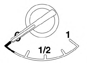
The gauge indicates the approximate fuel level in the tank.
The gauge may move slightly during braking, turning, acceleration, or going up or down hills.
The gauge needle returns to 0 (Empty) after the ignition switch is placed in the OFF position.
