Nissan Murano: Heater & Air Conditioning Control System :: Dtc/circuit Diagnosis / Front Blower Motor
CHECK FUSE
-
Ignition switch OFF.
-
Check 15A fuses [Nos. 17 and 27, located in fuse block (J/B)].
 NOTE:
NOTE:
Refer to Terminal Arrangement
Is the inspection result normal?
YES>>GO TO 2.
NO>>Replace the blown fuse after repairing the affected circuit.
CHECK FRONT BLOWER MOTOR POWER SUPPLY
-
Disconnect front blower motor connector.
-
Ignition switch ON.
-
Check voltage between front blower motor harness connector and ground.
+ − Voltage
(Approx.)Front blower motor Connector Terminal M112 4 Ground Battery voltage
Is the inspection result normal?
YES>>GO TO 3.
NO>>GO TO 6.
CHECK FRONT BLOWER MOTOR GROUND CIRCUIT
-
Ignition switch OFF.
-
Check continuity between front blower motor harness connector and ground.
Front blower motor — Continuity Connector Terminal M112 1 Ground Yes
Is the inspection result normal?
YES>>GO TO 4.
NO>>Repair harness or connector.
CHECK FRONT BLOWER MOTOR CONTROL SIGNAL CIRCUIT
-
Disconnect A/C auto amp. connector.
-
Check continuity between front blower motor harness connector and A/C auto amp. harness connector.
Front blower motor A/C auto amp. Continuity Connector Terminal Connector Terminal M112 3 M50 18 Yes
Is the inspection result normal?
YES>>GO TO 5.
NO>>Repair the harness or connector.
CHECK FRONT BLOWER MOTOR CONTROL SIGNAL
-
Reconnect front blower motor connector and A/C auto amp. connector.
-
Ignition switch ON.
-
Operate MODE switch to set air outlet to VENT.
-
Change fan speed from Lo to Hi, and check duty ratios between front blower motor harness connector and ground by using an oscilloscope.
NOTE:
Calculate drive signal duty ratio as shown in the figure.
T2 = Approx. 1.6 ms
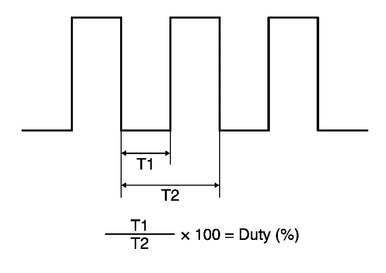
Front blower motor Condition Duty ratio
(Approx.)Connector Terminal Fan speed (manual)
VENT modeM112 3 1st 25 % 2nd 31 % 3rd 37 % 4th 45 % 5th 55 % 6th 65 % 7th 77 %
Is the inspection result normal?
YES>>Replace front blower motor. Refer to Removal and Installation.
NO>>Replace A/C auto amp. Refer to Removal and Installation.
CHECK FRONT BLOWER MOTOR RELAY GROUND CIRCUIT
-
Ignition switch OFF.
-
Check continuity between fuse block (J/B) harness connector and ground.
Fuse block (J/B) — Continuity Connector Terminal M68 13R Ground Yes
Is the inspection result normal?
YES>>GO TO 7.
NO>>Repair harness or connector.
CHECK FRONT BLOWER RELAY
Check front blower motor relay. Refer to Component Inspection (Front Blower Motor Relay).
Is the inspection result normal?
YES>>Repair harness or connector between front blower motor and fuse block (J/B).
NO>>Replace front blower relay.
CHECK FRONT BLOWER MOTOR
-
Connect battery voltage to terminal 4 of front blower motor.
-
Connect ground to terminal 1 of front blower motor.
Does the front blower fan operate?
YES>>Intermittent incident. Refer to Intermittent Incident.
NO>>Replace front blower motor. Refer to Removal and Installation.
CHECK BLOWER RELAY
-
Ignition switch OFF.
-
Disconnect front blower motor relay connector.
-
Check continuity between front blower motor relay terminals 3 and 5 when 12 V voltage is supplied between terminals 1 and 2.
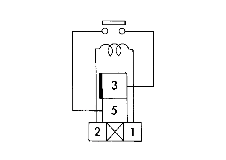
Front blower motor relay Voltage Continuity Terminals 3 5 ON Yes OFF No
Is the inspection result normal?
YES>>Inspection End.
NO>>Replace front blower motor relay.
 Door Motor Communication Circuit
Diagnosis Procedure
NOTE:
If all of door motor DTCs are detected, check this circuit.
CHECK EACH DOOR MOTOR COMMUNICATION SIGNAL
Ignition switch ON.
Check output waveform between A/C auto amp...
 Magnet Clutch
Component Function Check
CHECK MAGNET CLUTCH OPERATION
Perform auto active test of IPDM E/R. Refer to Diagnosis Description.
Does it operate normally?
YES>>
Inspection End...
Other information:
Nissan Murano (Z52) 2015-2024 Service Manual: System
System Description SYSTEM DIAGRAMSonar Control Unit Input Signal (CAN Communication) Component parts Signal description ABS actuator and electric unit (control unit) Transmits the Nissan Murano vehicle speed signal to sonar control unit via CAN communication...
Nissan Murano (Z52) 2015-2024 Service Manual: I-Da
System Description SYSTEM DIAGRAMADAS CONTROL UNIT INPUT/OUTPUT SIGNAL ITEMInput Signal Item Transmit unit Signal name Description ABS actuator and electric unit (control unit) CAN communication Nissan Murano Vehicle speed signal Receives the wheel speed of the four wheels Combination meter CAN communication System selection signal Receives a selection state of each item in “Driver Assistance” selected with the combination meter Steering angle sensor CAN communication Steering angle sensor signal Receives the amount of rotation, rotational angle, and rotational direction of the steering wheel Output Signal Item Reception unit Signal name Description Combination meter CAN communication Meter display signal I-DA status signal Transmits a signal and displays the status on the Nissan Murano vehicle information display Sonar control unit ITS communication Buzzer output signal Transmits a buzzer drive signal to activates the warning system buzzer FUNCTION DESCRIPTION The Intelligent Drive Alertness (I-DA) is controlled by the ADAS control unit control unit...
Categories
- Manuals Home
- Nissan Murano Owners Manual
- Nissan Murano Service Manual
- Indicator lights
- All-Wheel Drive (AWD) (if so equipped)
- Shift lock release
- New on site
- Most important about car
Driver and passenger supplemental knee air bag

Driver’s side
The knee air bag is located in the knee bolster, on the driver’s and passenger’s side. All of the information, cautions and warnings in this manual apply and must be followed. The knee air bag is designed to inflate in higher severity frontal collisions, although it may inflate if the forces in another type of collision are similar to those of a higher severity frontal impact. It may not inflate in certain collisions.

Passenger’s side